Cooling roll, method for manufacturing magnet material, ribbon shaped magnet material, magnetic powder and bonded magnet

a cooling roll and ribbon shaped technology, applied in the direction of magnetic materials, magnetic bodies, inorganic material magnetism, etc., can solve the problems of large difference in cooling rate at different sites on the surface layer, deterioration of magnetic properties, and inability to obtain stable magnetic properties

Inactive Publication Date: 2003-03-25
SEIKO EPSON CORP
View PDF11 Cites 7 Cited by
  • Summary
  • Abstract
  • Description
  • Claims
  • Application Information

AI Technical Summary

Problems solved by technology

On the free surface (the face opposed to the roll contact surface), on the contrary, the crystal grain size is coarsened due to slow cooling speed as compared with the roll contact surface, resulting in deterioration of magnetic properties.
Accordingly, large voids are formed between the plating layer and the quenched ribbon due to the large surface roughness when the plating layer obtained as described above is directly utilized as the surface layer, causing a large difference in the cooling rate at different sites on the surface layer.
As a result, the crystal grain size distribution in the quenched ribbon turns out to be heterogeneous to make it impossible to obtain stable magnetic properties.
In the machining step applied on the rotating cooling roll, however, uniform processing of the surface along the circumference direction is impossible due to eccentric rotation and mechanical shift and vibration of the cooling roll when the machining as described above is applied to the cooling roll, finally causing heterogeneous distribution of the thickness of the Cr plating layer obtained.
Consequently, the alloy of the quenched ribbon has a heterogeneous distribution of the crystal grain size to unable stable and high magnetic properties to be obtained.

Method used


Image

  • Cooling roll, method for manufacturing magnet material, ribbon shaped magnet material, magnetic powder and bonded magnet
  • Cooling roll, method for manufacturing magnet material, ribbon shaped magnet material, magnetic powder and bonded magnet
  • Cooling roll, method for manufacturing magnet material, ribbon shaped magnet material, magnetic powder and bonded magnet

Examples


example 1

A quenched ribbon with an alloy composition of (Nd.sub.0.9 Dy.sub.0.1).sub.8.9 Fe.sub.bal Co.sub.7.8 B.sub.5.6 Al.sub.0.7 was obtained by the method described below.

Each starting material of Nd, Fe, Co, B and Al was weighed, and the mixture was melted in an Ar gas to mold into a mother ingot, followed by cutting a sample with a mass of about 15 g.

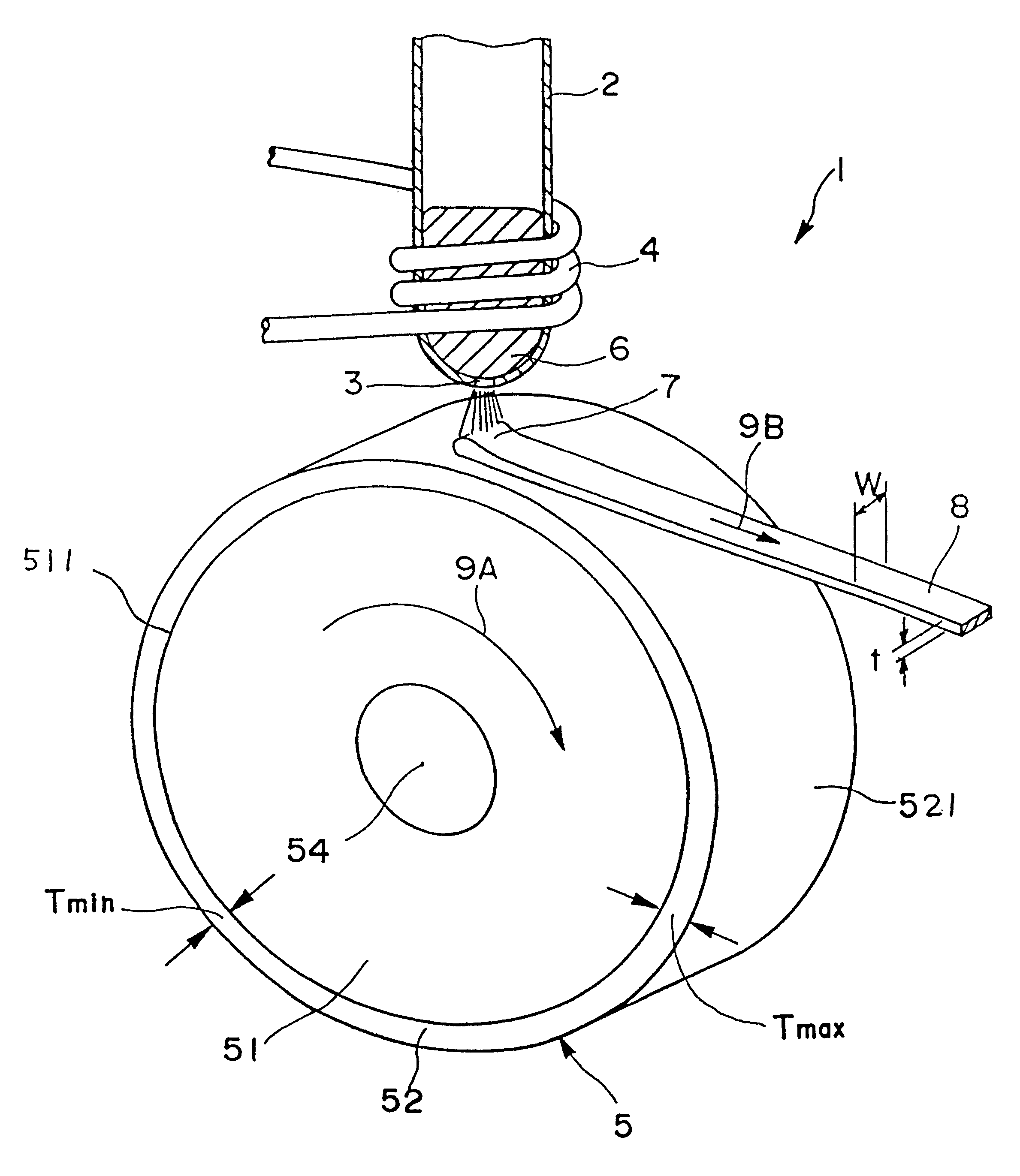
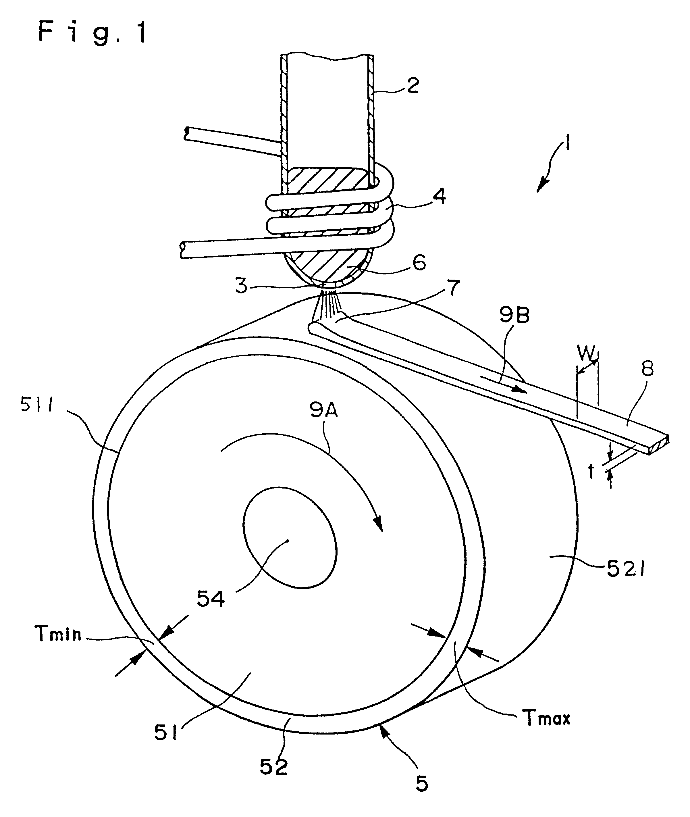
A quenching type ribbon manufacturing apparatus with the construction as shown in FIG. 1 was prepared, and the sample was placed into a quartz tube having a nozzle (an orifice) at its bottom.

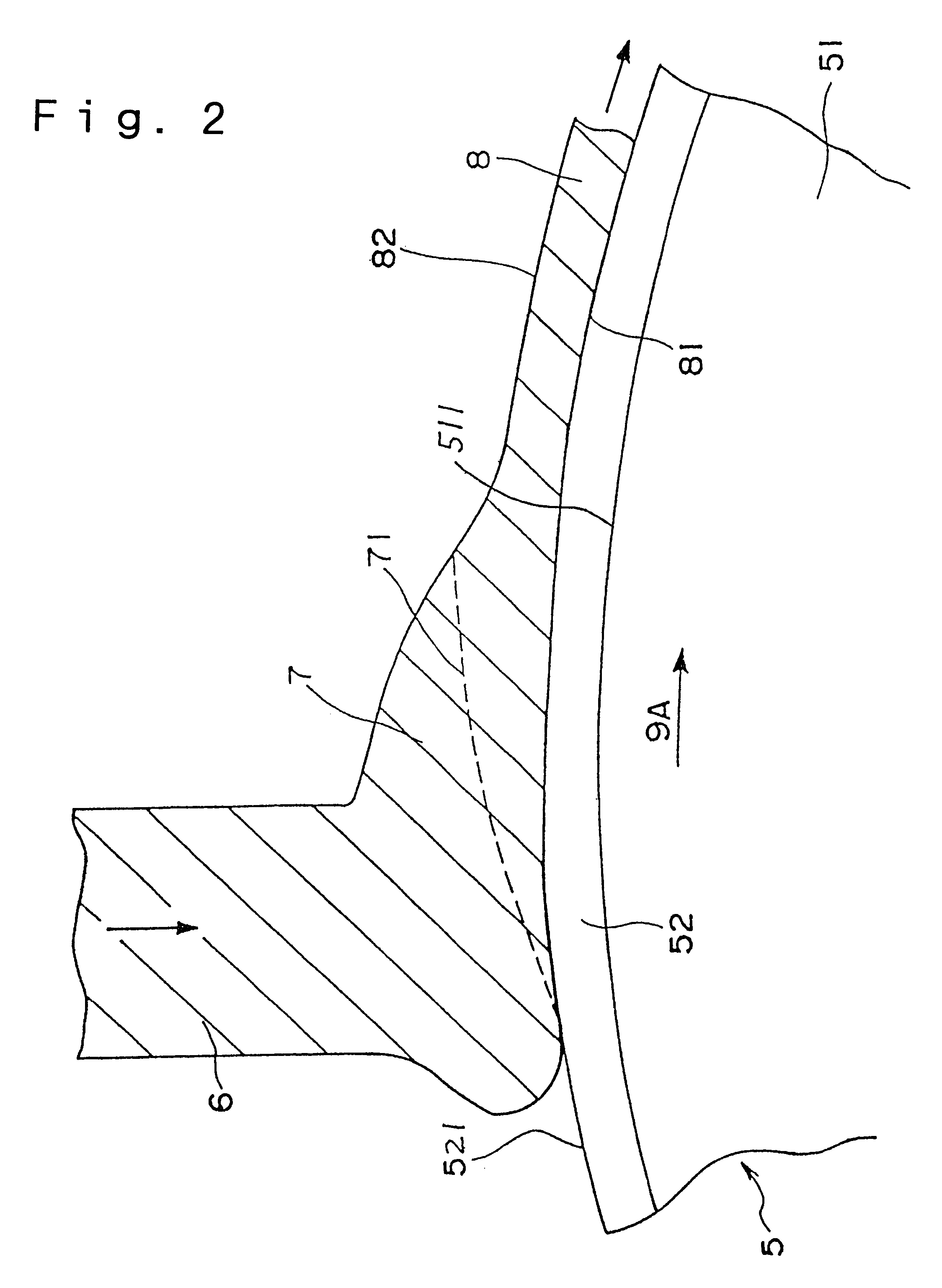
Each cooling roll 5 having respective surface layers 52 (Nos. 1 to 3, and 6) was obtained by the chemical vapor deposition (CVD) method on the circumference face of a roll base (200 mm in diameter and 30 mm in width) made of copper. Chemical vapor deposition was a heat CVD method. An appropriate synthetic reaction gas was selected depending on the material of the surface layer. The CVD temperature was about 800 to 1500.degree. C., although it is varied ...

example 2

After subjecting the quenched ribbons obtained in the condition Nos. 1 to 6 in Example 1 to a heat treatment at 680.degree. C. for 300 seconds, these quenched ribbons were pulverized to obtain magnetic powders.

X-ray diffraction was performed at a diffraction angle range of 20.degree. to 60.degree. using Cu-K.alpha. line for analyzing the phases of the magnetic powder obtained. It was possible to confirm a R.sub.2 (Fe.Co).sub.14 B type phase as a hard magnetic phase and a .alpha.-(Fe, Co) type phase as a soft magnetic phase, and these phases were confirmed to form composite microstructured (nano-composite microstructure) from the observation by a transmission type electron microscope (TEM).

The mean particle size of the magnetic powder obtained is shown in Table 3.

An epoxy resin (a binder resin) and a small amount of a hydrazine based antioxidant were mixed with each magnetic powder obtained as described above, and bonded magnet compositions (compounds) were prepared by kneading the m...

example 3

A quenched ribbon 8 with an alloy composition of (Nd.sub.0.7 Pr.sub.0.2 Dy.sub.0.1).sub.9.0 Fe.sub.bal Co.sub.8.0 B.sub.5.7 Si.sub.0.5 was obtained by the method described below.

A mixture of starting materials comprising Nd, Pr, Dy, Fe, Co, B and Si was at first weighed, and was melted in an induction melting furnace under the argon gas to melt and mold into a mother ingot. A sample with a mass of about 15 g was cut from the ingot.

Then, the quenching type ribbon manufacturing apparatus 1 was prepared, and the sample was placed into a quartz tube having a nozzle (circular orifice) 3 at the bottom.

A grinding and polishing processing was applied on the circumference face of the roll base (200 mm in diameter and 30 mm in width) made of copper, and six kinds of the roll bases 51 with a desired surface roughness Ra each were manufactured. The grinding processing was applied using a cylindrical grinding machine or a lathe, and buff polishing was also applied. A specular surface treatment w...


PUM

PropertyMeasurementUnit
surface roughnessaaaaaaaaaa
thicknessaaaaaaaaaa
radiusaaaaaaaaaa

Abstract

A cooling roll (5) for producing magnet materials, comprising a roll base material (51) and a surface layer (52) covering the outer periphery of the material, wherein the roll base material (51) is preferably formed of a metal material of a high heat conductivity, and the surface layer (52) is formed of a material lower in heat conductivity than the roll base material (51) and preferably formed of ceramics. The surface layer (52) satisfies the relation, 1.01<=Tmax/Tmin<=3, where Tmax is the maximum thickness of the surface layer (52), and Tmin the minimum thickness. The peripheral surface (511) of the roll base material (51) has a surface roughness Ra of 0.03 to 8 mum.

Description

The present invention relates to cooling roll, a method for manufacturing a magnet material, a ribbon shaped magnet material, a magnetic powder and a bonded magnet.A bonded magnet prepared by bonding a magnetic powder with a bonding resin is used for motors and various actuators by taking advantage of its wide degree of freedom of configuration.Magnet materials constituting the bonded magnet described above are manufactured by, for example, an quenching method using a quenching type ribbon manufacturing apparatus. The manufacturing method is called as a single roll method when the quenching type ribbon manufacturing apparatus comprises a single cooling roll.In the single roll method, a thin foil (ribbon) shaped magnet material, or a quenched ribbon is continuously manufactured by the steps comprising heating and melting a magnet material with a prescribed alloy composition, ejecting the molten liquid from a nozzle to allow it to collide with the circumference face of a rotating cool...

Claims


Application Information

Patent Timeline
Patent Type & Authority Patents(United States)
IPC IPC(8): B22D11/06H01F1/057H01F1/032H01F1/055
CPCB22D11/0651H01F1/0571H01F1/0551H01F41/02
Inventor ARAI, AKIRAKATO, HIROSHI
Owner SEIKO EPSON CORP
Why Eureka
Try Eureka