Permanent magnet and process for producing permanent magnet

a permanent magnet and permanent magnet technology, applied in the field of permanent magnets, to achieve the effect of improving residual magnetization and coercive force, reducing the amount of dy or tb used, and improving coercive for

Inactive Publication Date: 2011-02-24
NITTO DENKO CORP
View PDF6 Cites 7 Cited by
  • Summary
  • Abstract
  • Description
  • Claims
  • Application Information

AI Technical Summary

Benefits of technology

[0043]Further, according to the permanent magnet described in the above (5), the fine Dy particles or the fine Tb particles are unevenly distributed in grain boundaries of magnet particles, so that it becomes possible to sufficiently improve the coercive force due to Dy or Tb while decreasing the amount of Dy or Tb used.
[0044]Furthermore, according to the permanent magnet described in the above (6), the content of the above-mentioned fine Dy particles or fine Tb particles is from 0.01 to 8 wt %, so that it becomes possible to sufficiently improve the residual magnetization and coercive force by Dy or Tb while decreasing the amount of Dy or Tb used.
[0045]In addition, according to the method for manufacturing a permanent magnet described in the above (7), oxidation of the pulverized magnet raw material can be prevented by mixing the magnet raw material with the rust preventive oil. Further, it becomes possible to unevenly distribute a slight amount of the Dy compound or the Tb compound dissolved in the mixed rust preventive oil in grain boundaries of magnet particles, whereby it becomes possible to manufacture the permanent magnet improved in the coercive force due to Dy or Tb while decreasing the amount of Dy or Tb used. Furthermore, it can be prevented that Dy or Tb is solid-solutionized in the magnet particles to decrease the residual magnetization.
[0046]Further, according to t

Problems solved by technology

However, Dy is a rare metal, and the locality thereof is limited, so that it i

Method used


Image

  • Permanent magnet and process for producing permanent magnet
  • Permanent magnet and process for producing permanent magnet
  • Permanent magnet and process for producing permanent magnet

Examples


Embodiment Construction

[0054]A specific embodiment of a permanent magnet and a method for manufacturing the permanent magnet according to the invention will be described below in detail with reference to the drawings.

[0055]Constitution of Permanent Magnet

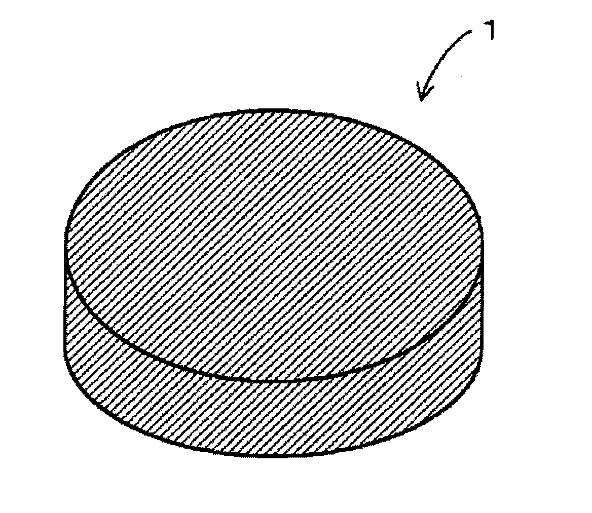
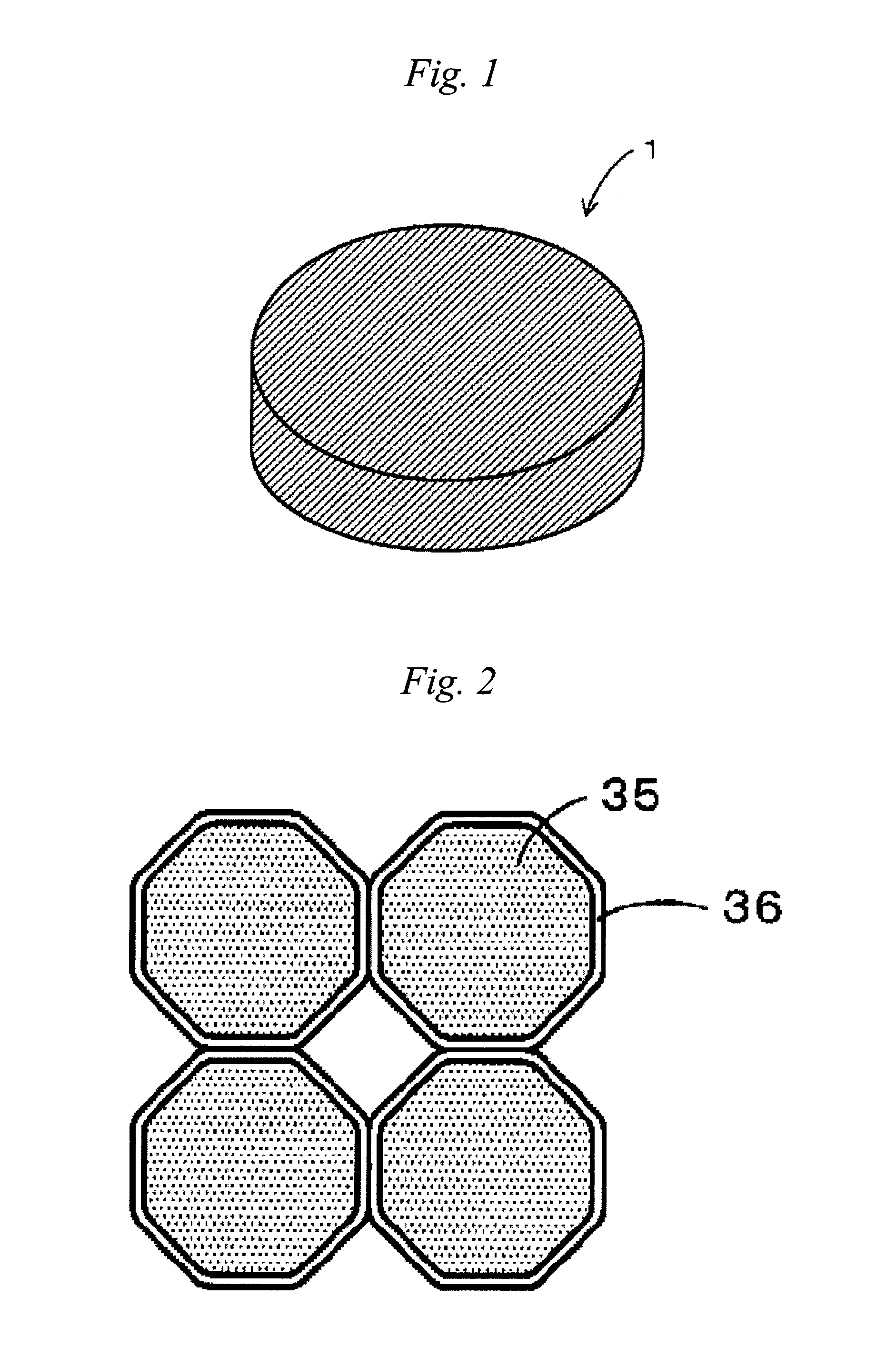
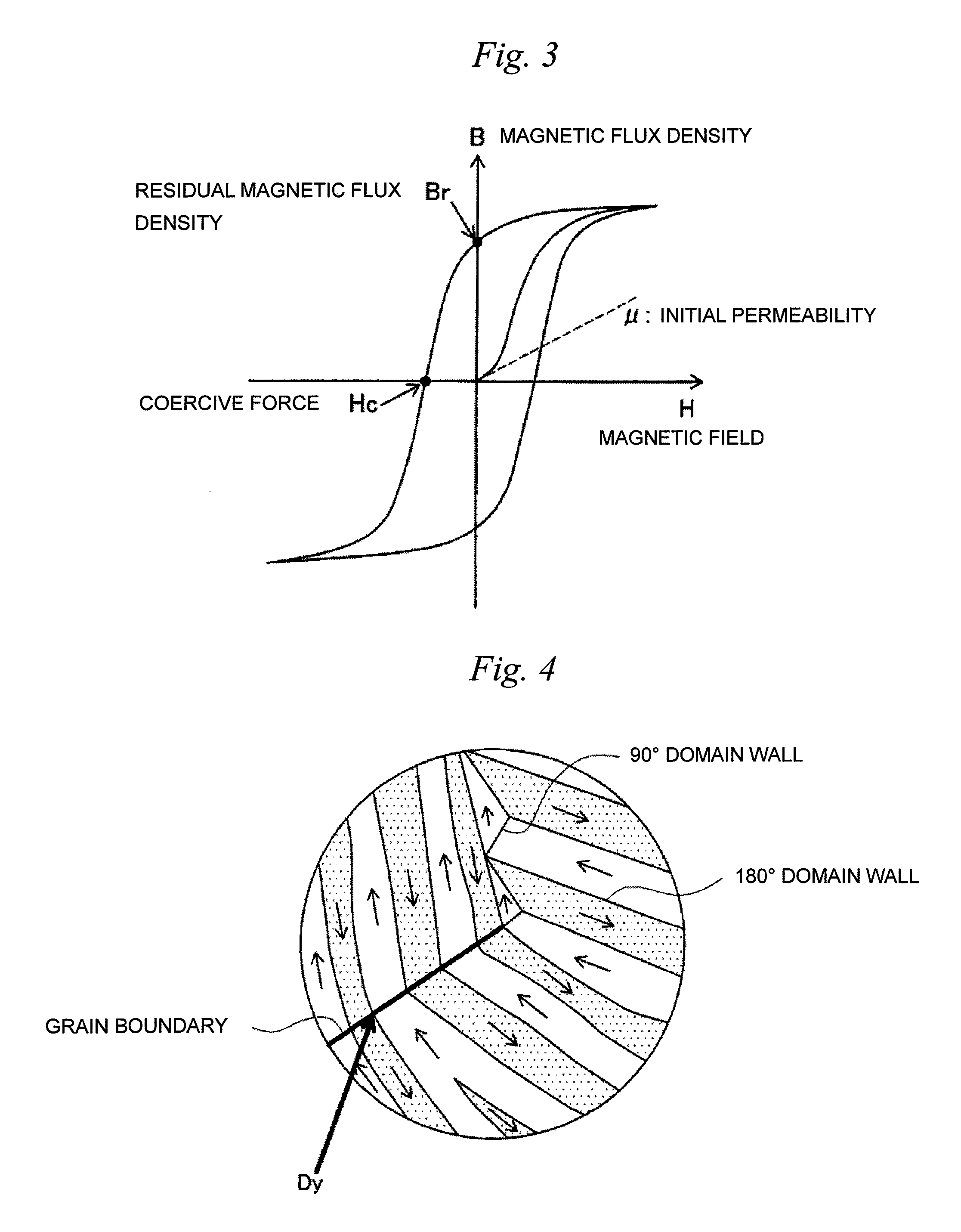
[0056]First, a constitution of a permanent magnet 1 will be described using FIGS. 1 to 4.

[0057]The permanent magnet 1 according to this embodiment is a Nd—Fe—B-based magnet. Further, Dy (dysprosium) for increasing the coercive force of the permanent magnet 1 is added. Incidentally, the contents of respective components are regarded as Nd: 27 to 30 wt %, a Dy component contained in a Dy compound (or a Tb component contained in a Tb compound): 0.01 to 8 wt %, B: 1 to 2 wt %, and Fe (electrolytic iron): 60 to 70 wt %. Furthermore, the permanent magnet 1 according to this embodiment has a cylindrical shape as shown in FIG. 1, but the shape of the permanent magnet 1 varies depending on the shape of a cavity used in molding. FIG. 1 is an overall view showing th...


PUM

PropertyMeasurementUnit
Grain boundaryaaaaaaaaaa

Abstract

The present invention relates to a permanent magnet manufactured by steps of: pulverizing a magnet raw material; mixing the pulverized magnet raw material with a rust preventive oil in which a Dy compound or a Tb compound is dissolved, thereby preparing a slurry; compression molding the slurry to form a molded body; and sintering the molded body.

Description

TECHNICAL FIELD[0001]The present invention relates to a permanent magnet and a method for manufacturing the permanent magnet.BACKGROUND ART[0002]In recent years, a reduction in size and weight, an increase in power and an increase in efficiency have been required for permanent magnetic motors used in hybrid cars, hard disk drives or the like. Then, in realizing a reduction in size and weight, an increase in power and an increase in efficiency in the above-mentioned permanent magnetic motors, a reduction in film thickness and further improvement in magnetic characteristics have been required for permanent magnets buried in the permanent magnetic motors. Incidentally, as the permanent magnets, there are ferrite magnets, Sm—Co-based magnets, Nd—Fe—B-based magnets, Sm2Fe17Nx-based magnets and the like. In particular, Nd—Fe—B-based magnets having high coercive force are used as the permanent magnets for the permanent magnet motors.[0003]Here, as a method for manufacturing the permanent m...

Claims


Application Information

Patent Timeline
IPC IPC(8): H01F7/02B28B1/24B22F1/10
CPCB22F1/0059B22F2003/023C22C38/002C22C38/005H01F41/0293H01F1/0577H01F7/02H01F41/0266H01F1/0572B22F1/10
Inventor OZEKI, IZUMIKUME, KATSUYANAKAYAMA, JUNICHIFUKUDA, YUUKIHOSHINO, TOSHINOBUHORIO, TOMOKAZU
Owner NITTO DENKO CORP
Why Eureka
Try Eureka