Eureka AIR delivers breakthrough ideas for toughest innovation challenges, trusted by R&D personnel around the world.

Cutting mechanism for plastic pipe

A technology of cutting mechanism and plastic pipe fittings, applied in the field of pipe fittings processing, can solve problems such as poor effect and low feeding efficiency, and achieve high efficiency and good effect.

Active Publication Date: 2017-08-04
湖州优研知识产权服务有限公司
View PDF6 Cites 14 Cited by
  • Summary
  • Abstract
  • Description
  • Claims
  • Application Information

AI Technical Summary

Problems solved by technology

[0004] The existing elongated pipe needs to be cut for processing. The existing cutting method is generally to manually push the pipe, and the other end is automatically equipped with a cutting mechanism for automatic cutting. The manual push is low in efficiency and poor in effect.

Method used


Image

  • Cutting mechanism for plastic pipe
  • Cutting mechanism for plastic pipe
  • Cutting mechanism for plastic pipe

Examples


Embodiment

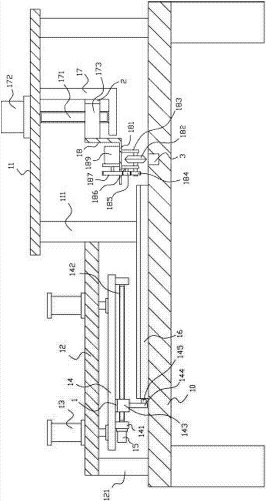
[0022] Example: see Figure 1 to Figure 3 As shown, a plastic pipe fitting cutting mechanism includes a frame 10, a cutting connecting plate 11 is arranged on the upper right side of the top plate of the frame 10, and a plurality of support columns 111 are fixed on the bottom surface of the cutting connecting plate 11, and the supporting columns 111 Be fixed on the top surface of the top plate of the frame 10, push the connecting plate 12 on the left top of the top plate of the frame 10, push the left side bottom surface of the connecting plate 12 to be fixed with a plurality of left support columns 121, and the left support columns 121 are fixed on On the top plate of the frame 10, push the right side of the connecting plate 12 to be fixed on the support column 111 below the left end of the cutting connecting plate 11;

[0023] The top surface of described pushing connecting plate 12 is fixed with a plurality of lifting cylinders 13, and the push rod of lifting cylinder 13 pa...


PUM


Abstract

The invention discloses a cutting mechanism for a plastic pipe. The cutting mechanism comprises a rack. A cutting connecting plate is arranged above the right side of a top plate of the rack. Multiple supporting pillars are fixed to the bottom face of the cutting connecting plate. The supporting pillars are fixed to the top face of the top plate of the rack. A pushing connecting plate is located above the left side of the top plate of the rack. Multiple left supporting pillars are fixed to the bottom face of the left side of the pushing connecting plate. The left supporting pillars are fixed to the top plate of the rack. The right side of the pushing connecting plate is fixed to the supporting pillar below the left end of the cutting connecting plate. Multiple lifting air cylinders are fixed to the top face of the pushing connecting plate. Push rods of the lifting air cylinders penetrate the pushing connecting plate and are fixedly provided with a lifting plate. Limiting plates are fixed to the two ends of the bottom face of the lifting plate. The two ends of a transverse screw rod are hinged to the two limiting plates, and a drive motor is fixed to the outer side wall of one limiting plate. The cutting mechanism can be used for automatically pushing the pipe and automatically cutting the pipe and is high in efficiency and good in effect.

Description

[0001] Technical field: [0002] The invention relates to the technical field of pipe fitting processing, and more specifically relates to a cutting mechanism for plastic pipe fittings. [0003] Background technique: [0004] The existing elongated pipe needs to be cut for processing. The existing cutting method is generally to manually push the pipe, and the other end is automatically equipped with a cutting mechanism for automatic cutting. The manual push is low in efficiency and poor in effect. [0005] Invention content: [0006] The purpose of the present invention is to provide a cutting mechanism for plastic pipe fittings, which can automatically push the pipe fittings for automatic cutting, with high efficiency and good effect. [0007] Technical solutions of the present invention are as follows: [0008] A cutting mechanism for plastic pipe fittings, comprising a frame, a cutting connecting plate is arranged on the upper right side of the top plate of the frame, and ...

Claims


Application Information

Patent Timeline
Patent Type & Authority Applications(China)
IPC IPC(8): B26D1/18B26D7/06B26D5/06
CPCB26D1/18B26D5/06B26D7/0608
Inventor 王海峰
Owner 湖州优研知识产权服务有限公司
Why Eureka
Eureka Blog
Learn More