Automatic balancing propeller used for ships, vehicles and aircrafts

An automatic balancing and aircraft technology, applied in aircraft, vehicle parts, flight direction control, etc., can solve the problem of increased friction and buoyancy of diaphragms and sliding valves, reducing the sensitivity of automatic balancing propellers for ships, vehicles, and aircraft and other problems, to achieve the effect of volume and weight reduction, and sliding valve sensitivity

Active Publication Date: 2017-08-04
河南星汉矢量推力器制造有限公司
View PDF9 Cites 5 Cited by
  • Summary
  • Abstract
  • Description
  • Claims
  • Application Information

AI Technical Summary

Problems solved by technology

[0002] The patent application with the application publication number of CN 105836109 A discloses a self-balancing propeller for ships, vehicles and aircraft. The self-balancing propeller for ships, vehicles and aircraft includes two water-holding boxes, two boxes The high-pressure air chamber is set above the box, and a partition is set in the middle of the high-pressure air chamber. The partition divides the high-pressure air chamber into two chambers, one chamber is connected to the high-pressure air energy storage bag, and the other chamber is connected to the injection chamber. In the middle of the partition, there is a strip-shaped hole in the partition to connect the two chambers. On one side of the partition, a sliding valve that can slide up and down is provided. The strip-shaped hole of the sliding valve, the strip-shaped hole of the sliding valve and the strip-shaped hole of the partition are on the same straight line, and the lower end of the sliding valve is connected to the float; since the two sides of the partition and the sliding valve are respectively connected with the high-pressure air energy storage bag and the injection pipe, the two sides The pressure difference squeezes the diaphragm and the sliding valve together, which increases the friction between the diaphragm and the sliding valve, and the buoyancy required for the sliding valve to rise or fall is relatively large, which reduces the self-balancing propeller used by ships, vehicles, and aircraft. sensitivity

Method used


Image

  • Automatic balancing propeller used for ships, vehicles and aircrafts

Examples


Embodiment Construction

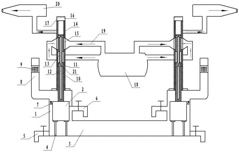
[0014] The self-balancing propeller for ships, vehicles, and aircrafts includes a pressure vessel 18, a high-pressure air intake pipe 19, a high-pressure injection bag 20, a water container 1, a float 2 and a connector 3, and the middle and lower parts of the water container 1 are respectively provided with oil pollution discharge valves 6 And replace the drain valve 5, the water container 1 is provided with a drop-limiting top column 4, the drop-limiting top column 4 is located below the float 2, the float 2 is a hollow structure, and the float 2 top is provided with a float water injection weight adjustment port 7, and the top of the water container 1 Water injection pipe 8 is set, and air filter cover 9 is arranged in water injection pipe 8, and described water container 1 is provided with elongated float observation window, so that with the initial position of setting float 2.

[0015] The upper end of the water container 1 is provided with an outer casing 14, and the middl...


PUM


Abstract

The invention relates to an automatic balancing propeller used for ships, vehicles and aircrafts. The automatic balancing propeller used for the ships, the vehicles and the aircrafts comprises a pressure container, a high-pressure gas inlet pipe, a high-pressure jet bag, a water container, a floater and a communicating vessel; an outer sleeve pipe is arranged at the upper end of the water container; four vents are formed in the middle of the outer sleeve pipe; two positively-faced vents communicate with the high-pressure gas inlet pipe; the other two vents communicate with the high-pressure jet bag; a sliding valve is arranged in the outer sleeve pipe; the floater is connected with the lower end of the sliding valve; and sliding valve supplying gas outlet grooves are formed in the middle of the sliding valve. According to the automatic balancing propeller, the pressure on the two sides of the sliding valve is the same and is not affected by the unidirectional pressure of the high-pressure air, and the bidirectional pressure is mutually offset, so that the sliding valve is more sensitive, and meanwhile the volumes and weights of the floater and the water container are correspondingly reduced.

Description

technical field [0001] The invention relates to an automatic balancing propeller for ships, vehicles and aircrafts. Background technique [0002] The patent application with the application publication number of CN 105836109 A discloses a self-balancing propeller for ships, vehicles and aircraft. The self-balancing propeller for ships, vehicles and aircraft includes two water-holding boxes, two boxes The high-pressure air chamber is set above the box, and a partition is set in the middle of the high-pressure air chamber. The partition divides the high-pressure air chamber into two chambers, one chamber is connected to the high-pressure air energy storage bag, and the other chamber is connected to the injection chamber. In the middle of the partition, there is a strip-shaped hole in the partition to connect the two chambers. On one side of the partition, a sliding valve that can slide up and down is provided. The strip-shaped hole of the sliding valve, the strip-shaped hole ...

Claims


Application Information

Patent Timeline
Patent Type & Authority Applications(China)
IPC IPC(8): B63B39/08B64C15/02B64C15/14B64C29/04B62D37/00
CPCB62D37/00B63B39/08B64C15/02B64C15/14B64C29/04
Inventor 王金海
Owner 河南星汉矢量推力器制造有限公司
Why Eureka
Try Eureka