
A coaxial dual-rotor structure

A technology of coaxial double rotors and rotors, applied in the field of aviation systems, can solve problems such as unseen coaxial double rotor structures, and achieve the effects of simple structure, high control precision, and low manufacturing difficulty.

Active Publication Date: 2019-06-11
QINGAN GRP
View PDF5 Cites 1 Cited by
  • Summary
  • Abstract
  • Description
  • Claims
  • Application Information

AI Technical Summary

Problems solved by technology

[0004] A kind of coaxial double-rotor structure that the present invention mentions has not yet seen

Method used


Image

  • A coaxial dual-rotor structure
  • A coaxial dual-rotor structure
  • A coaxial dual-rotor structure

Examples


Embodiment Construction

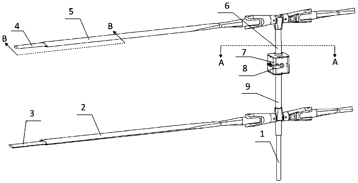
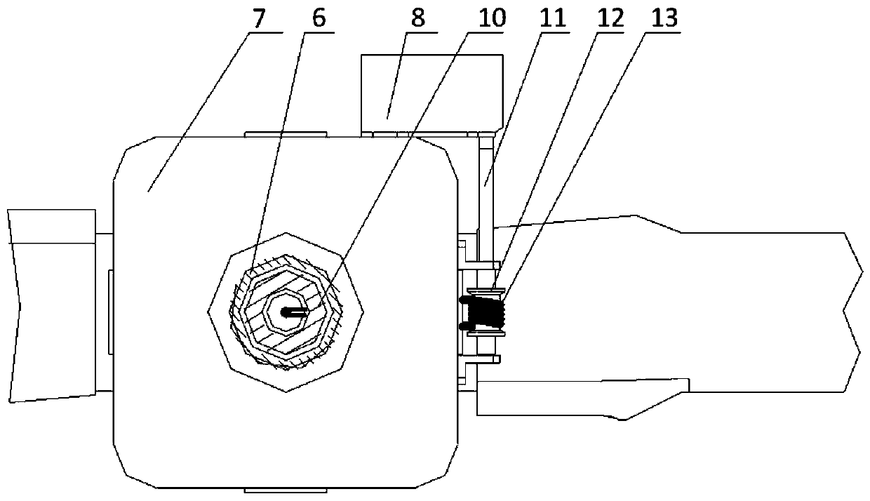
[0029] A coaxial double-rotor structure is provided, which comprises a coaxial upper main rotor 5, a lower main rotor 2, an upper rotor shaft 6, a lower rotor shaft 9, a central shaft 1, an upper bevel gear 16, a reversing bevel gear 17, Lower bevel gear 20, upper winglet 4, lower winglet 3;

[0030] The central shaft 1 includes an upper central shaft 10, a coupling 20 and a lower central shaft 21; the upper central shaft 10 and the lower central shaft 21 are connected by a coupling 20, and the coupling 20 can be connected to the upper central shaft 10 and the lower central shaft 21. The lower central shaft 21 rotates; the middle of the coupling 20 is provided with a hollow cavity, the upper central shaft 10, and the lower central shaft 21 are all provided with hollow cavities, and the hollow cavities of the upper central shaft 10, the coupling 20 and the lower central shaft 21 are mutually connected;

[0031] The middle part of the upper central shaft 10 protrudes along the ...


PUM


Abstract

The invention relates to a coaxial double-rotor-wing structure. The two layers of rotor wings of the coaxial double-rotor-wing structure are provided with telescopic small wing bodies correspondingly. A motor is arranged between the two layers of rotor wings, a stay wire is arranged on a motor rotating shaft, the two ends of the stay wire are connected with the upper small rotor wing body and the lower small rotor wing body corresponding, and the stay wire can be driven through rotating of the motor in the two directions to enable the diameter of one of the upper and lower rotor wings to be increased and the diameter of the other of the upper and lower rotor wings to be decreased, so that inverted toque between the upper and lower rotor wings of a coaxial double-rotor-wing type helicopter is changed, and the purpose of controlling yawing of the coaxial double-rotor-wing type helicopter is achieved.

Description

technical field [0001] The invention relates to a coaxial double-rotor helicopter structure, which belongs to the technical field of aviation systems. Background technique [0002] The heading control of most existing coaxial dual-rotor helicopters is mainly by changing the pitch angle of the upper and lower rotors so that the upper and lower rotors generate a reaction torque difference to realize the heading change of the coaxial dual-rotor helicopters. [0003] The German "seamos" coaxial dual-rotor unmanned helicopter changes the anti-torque of the rotor by placing a drag plate on the tip of the rotor to realize the yaw control of the coaxial helicopter. The windward area of ​​the drag plate at the tip of the rotor will result in a difference in the reaction torque of the two rotors, changing the heading of the helicopter. [0004] A kind of coaxial double-rotor structure that the present invention mentions has not seen yet. Contents of the invention [0005] purpose ...

Claims


Application Information

Patent Timeline
Patent Type & Authority Patents(China)
IPC IPC(8): B64C27/10B64C27/32B64C27/473
CPCB64C27/10B64C27/32B64C27/473
Inventor 董鹰
Owner QINGAN GRP
Learn More