Shoe last sample plate placement device for leather shoe production

The technology of a last and a template is applied in the field of a last template placement device for leather shoe making, and can solve the problems of inconvenient placement and storage of the last.

Active Publication Date: 2017-08-04
郑海涛
View PDF10 Cites 8 Cited by
  • Summary
  • Abstract
  • Description
  • Claims
  • Application Information

AI Technical Summary

Problems solved by technology

[0006] In order to overcome the disadvantage of inconvenient placement and storage of lasts in the prior art, the present invention aims to solve the technical problem of providing a last template placement device for leather shoe making that can conveniently store lasts

Method used


Image

  • Shoe last sample plate placement device for leather shoe production
  • Shoe last sample plate placement device for leather shoe production
  • Shoe last sample plate placement device for leather shoe production

Examples


Embodiment 1

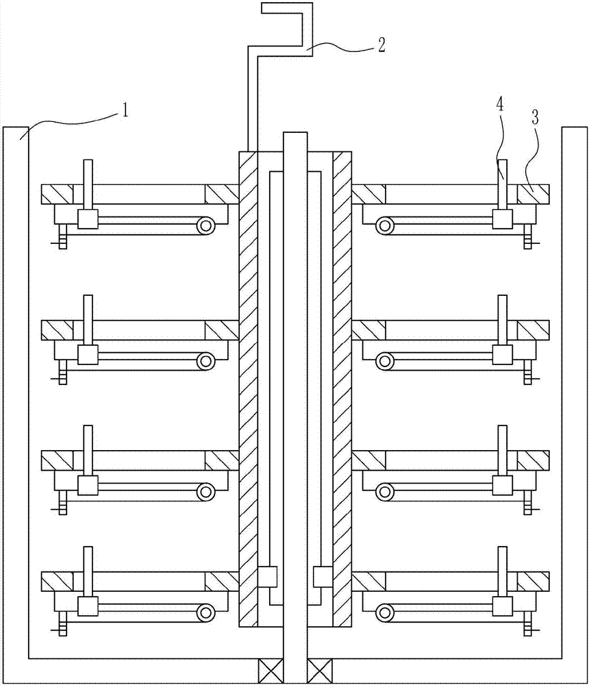
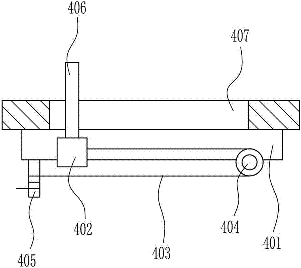
[0040] A device for placing a last model for making leather shoes, such as Figure 1-7 As shown, it includes a placing box 1, a rotating lifting mechanism 2, a placing plate 3 and a clamping mechanism 4. The placing box 1 is connected with a rotating lifting mechanism 2, and the rotating lifting mechanism 2 is evenly connected with a placing plate 3. On the placing plate 3 Both are connected with a clamping mechanism 4 .

Embodiment 2

[0042] A device for placing a last model for making leather shoes, such as Figure 1-7 As shown, it includes a placing box 1, a rotating lifting mechanism 2, a placing plate 3 and a clamping mechanism 4. The placing box 1 is connected with a rotating lifting mechanism 2, and the rotating lifting mechanism 2 is evenly connected with a placing plate 3. On the placing plate 3 Both are connected with a clamping mechanism 4 .

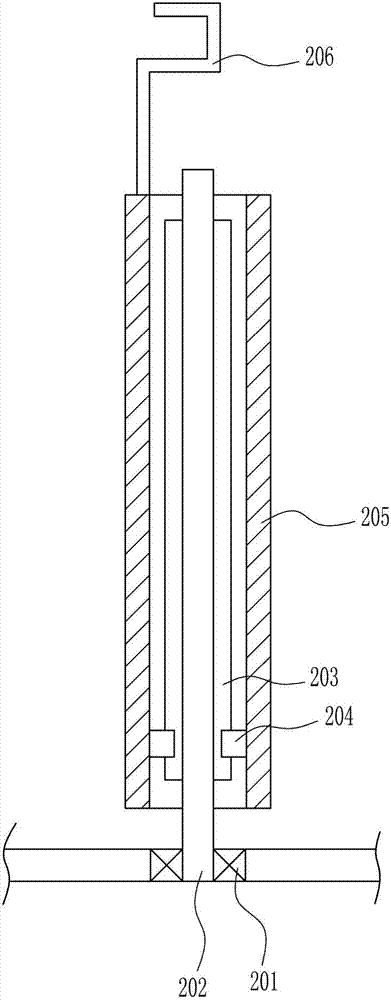
[0043] The rotary lifting mechanism 2 includes a bearing seat 201, a rotating rod 202, the first slide rail 203, the first slide block 204, a rotating cylinder 205 and a handle 206, and a bearing seat 201 is installed in the middle of the bottom of the placing case 1. On the bearing seat 201 Connected with a rotating rod 202, the left and right sides of the rotating rod 202 are connected with a first slide rail 203, the first slide rail 203 is slidably connected with a first slider 204, the first slide rail 203 and the first slider 204 Cooperate, the outer ...

Embodiment 3

[0045] A device for placing a last model for making leather shoes, such as Figure 1-7 As shown, it includes a placing box 1, a rotating lifting mechanism 2, a placing plate 3 and a clamping mechanism 4. The placing box 1 is connected with a rotating lifting mechanism 2, and the rotating lifting mechanism 2 is evenly connected with a placing plate 3. On the placing plate 3 Both are connected with a clamping mechanism 4 .

[0046] The rotary lifting mechanism 2 includes a bearing seat 201, a rotating rod 202, the first slide rail 203, the first slide block 204, a rotating cylinder 205 and a handle 206, and a bearing seat 201 is installed in the middle of the bottom of the placing case 1. On the bearing seat 201 Connected with a rotating rod 202, the left and right sides of the rotating rod 202 are connected with a first slide rail 203, the first slide rail 203 is slidably connected with a first slider 204, the first slide rail 203 and the first slider 204 Cooperate, the outer ...


PUM


Abstract

The invention relates to a placement device, in particular to a shoe last sample plate placement device for leather shoe production, and aims to solve the technical problem about provision of the shoe last sample plate placement device for the leather shoe production which can place and store shoe lasts conveniently. In order to solve the technical problem, the invention provides the shoe last sample plate placement device for the leather shoe production, which comprises a placement box, a rotary lifting mechanism, placement plates, clamping mechanisms and the like; the placement box is connected with the rotary lifting mechanism; the rotary lifting mechanism is connected with the placement plates uniformly; each placement plate is connected with a clamping mechanism. According to the shoe last sample plate placement device for the leather shoe production, the rotary lifting mechanism is arranged first, so that the rotary lifting mechanism drives the placement plates to move upwards; therefore, the placement plates can be moved out of the placement box, and then the shoe lasts are respectively placed on the placement plates.

Description

technical field [0001] The invention relates to a placement device, in particular to a last template placement device for making leather shoes. Background technique [0002] Leather shoes refer to footwear with natural leather as the upper and leather or rubber, plastic, PU foam, PVC, etc. as the sole, which are processed by sewing, gluing or injection molding. Leather shoes are air-permeable, moisture-absorbing, have good hygienic performance, and are the shoes with the highest grade among all kinds of shoes and boots. [0003] At present, the last is needed in the production and production of leather shoes. The quality of the last determines the comfort and aesthetics of the shoes. However, when people are making leather shoes, there is no specific place to store the last after using it. It is easy to cause wear and damage to the last, and the models of the last are different, so it is inconvenient to find when needed. [0004] Therefore, there is an urgent need to devel...

Claims


Application Information

Patent Timeline
Patent Type & Authority Applications(China)
IPC IPC(8): B65D25/02B65D25/10B65D43/26B65D43/18
CPCB65D25/02B65D25/10B65D43/18B65D43/26
Inventor 杨国祥
Owner 郑海涛
Why Eureka
Try Eureka