
Knotting mechanisms and creels

A creel and path technology, applied in transportation and packaging, textiles and papermaking, thin material processing, etc., can solve the problems of hard work and labor, and achieve the effect of effortless physical strength and simple operation

Active Publication Date: 2019-11-26
KARL MAYER ROTAL SRL
View PDF11 Cites 0 Cited by
  • Summary
  • Abstract
  • Description
  • Claims
  • Application Information

AI Technical Summary

Problems solved by technology

However, said knotting is relatively laborious and strenuous for the operator

Method used


Image

  • Knotting mechanisms and creels
  • Knotting mechanisms and creels
  • Knotting mechanisms and creels

Examples


Embodiment Construction

[0033] Referring first to a very schematic illustration of a creel 1 as described in Figure 9 as shown in.

[0034] The creel 1 has two beam supports 2 , 3 , wherein a section warp beam 4 , 5 is arranged in each beam support 2 , 3 . Partial yarn sheets (teilfadenschar) 6 , 7 are withdrawn from each partial warp beam 4 , 5 . The slivered yarn sheets 6 , 7 are guided by deflection rollers 8 , 9 and joined after the last deflection roller 9 to form a yarn sheet 10 . The yarn sheet 10 is then delivered to the doubling device (or other processing mechanism) along the direction of arrow 11 . A device for feeding slurry can also be connected upstream of the paralleling device.

[0035] Of course, more than the two illustrated warp beam supports 2 , 3 can also be provided, so that more than two section warp beams 4 , 5 can also be accommodated in the creel 1 .

[0036] When the section warp beams 4, 5 need to be replaced (because, for example, the section warp beams 4, 5 are work...


PUM


Abstract

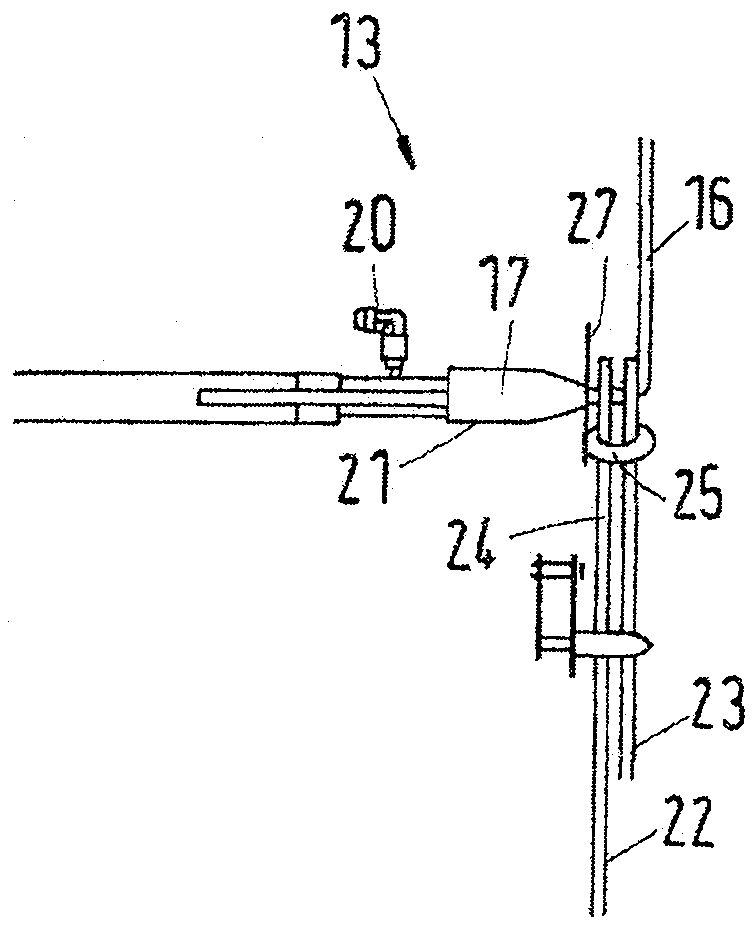
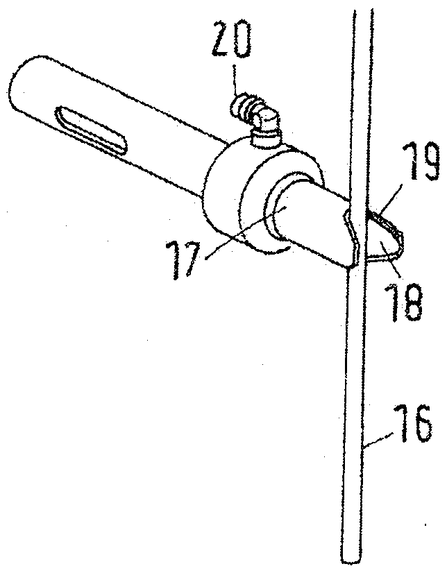
The invention relates to a knot device (13) having a first path for an end of a first thread bundle (16) and a second path for an initial thread of a second thread bundle (22), wherein the second path (21) ), which is hollow and has a suction opening, the first path is arranged in front of the suction opening, the suction opening is connected to a suction device (20) and the mandrel (17) is displaceable relative to the first path.

Description

technical field [0001] The present invention relates to knotting mechanisms for yarn bundles. [0002] Furthermore, the invention relates to a creel with at least one warp beam support and a creel output at which such a knotting mechanism is arranged. Background technique [0003] The invention is described below in terms of a parallel arrangement, but should not be restricted thereto. [0004] In the doubling mechanism, the pieces drawn from several section warp beams are combined into one warp beam. If desired, the yarn sheet or the combined yarn sheet which is wound onto the warp beam can also be subjected to further treatments, for example size can be applied. [0005] If it is necessary to replace the conveyed yarn sheet (for example because one or more section warp beams are working without load or because warp beams with other yarns should be produced), the end of the yarn sheet on the reel is usually separated from the The beginning of the newly delivered yarn she...

Claims


Application Information

Patent Timeline
Patent Type & Authority Patents(China)
IPC IPC(8): B65H69/04
CPCB65H69/04B65H2701/31D02H11/00D03J1/18
Inventor E.保利
Owner KARL MAYER ROTAL SRL
Learn More