
Load balancing control device and method for outriggers of bridge erecting machine

A technology of equalizing device and bridge erecting machine, which is applied in the direction of erecting/assembling bridges, bridges, and bridge construction, etc., can solve the problems of inability to anchor, move laterally, and cannot be inserted.

Active Publication Date: 2017-08-04
CHINA RAILWAY ENG MASCH RES & DESIGN INST CO LTD
View PDF6 Cites 3 Cited by
  • Summary
  • Abstract
  • Description
  • Claims
  • Application Information

AI Technical Summary

Problems solved by technology

[0005] The present invention mainly solves the problem that in the prior art, when the outrigger legs of the bridge erecting machine rigidly support the main girder, the support rollers on both sides of the same main girder are under unbalanced force, and the phenomenon that the support rollers and the main girder are prone to detachment under certain working conditions To solve the technical problems, a load balance control device and method for the outriggers of the bridge erecting machine are provided.
[0006] Another object of the present invention is to solve the problem in the prior art that after the anchorage of the main girder and the outrigger of the bridge erecting machine is connected by a fixed pin shaft, the lateral movement does not move after the bolt appears, or the anchor pin shaft and the support cannot be inserted after the lateral movement. The technical problem that the anchor rod at the lower part of the leg is misaligned with the anchor hole of the erected box girder or bridge pier and cannot be anchored, provides a load balancing control device and method for the outrigger of a bridge erecting machine

Method used


Image

  • Load balancing control device and method for outriggers of bridge erecting machine
  • Load balancing control device and method for outriggers of bridge erecting machine
  • Load balancing control device and method for outriggers of bridge erecting machine

Examples


Embodiment

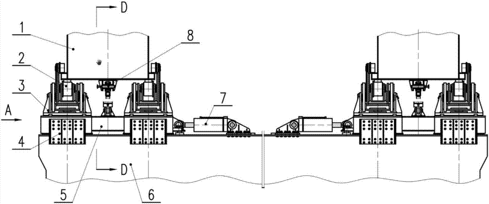
[0041] see figure 1 According to the present invention, the outrigger of the bridge-erecting machine is balanced under load and the main girder and outrigger anchoring device include a supporting wheel assembly (2), a hinge support (3), a buckle assembly (4), a traverse device (5), Traversing oil cylinder (7), anchoring device (8) and so on.

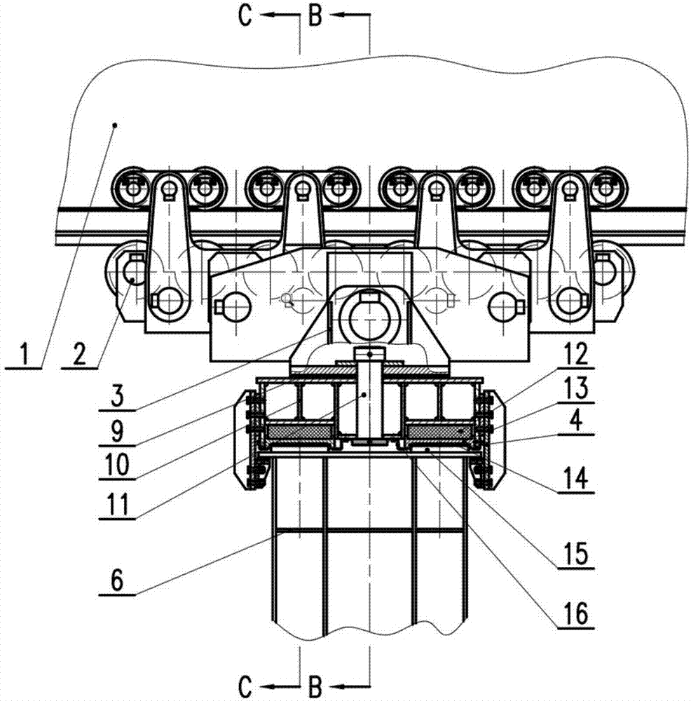
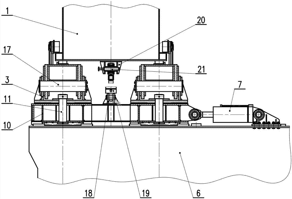
[0042] see figure 2 , image 3 with Figure 4 , the traversing device (5) is mainly composed of a traversing platform (10), a hinge support central axis (11), a left rubber support (12), a right rubber support (22), a card groove plate (13), a traversing It is composed of wear-reducing plate (14), traverse support (15), and sealing plate (16).

[0043] In order to ensure relative movement between the outrigger of the bridge erecting machine and the main girder (1), the outrigger adopts the supporting wheel assembly (2) to support the main girder (1) and is connected by rolling, that is, the main girder (1) It is pressed on the supp...


PUM


Abstract

The invention relates to a load balancing control device and method, in particular to a load balancing control device and method for outriggers of a bridge erecting machine, and belongs to the field of bridge erecting construction equipment. By the customized amount of deformation of a left rubber bearing and a right rubber bearing of different stiffnesses, deformation of bearing a cross girder by the outriggers through the cantilever force is remedied, and the stress of supporting wheels on the two sides is coordinated, so that the purpose of load balancing is achieved; a supporting and lifting wheel assembly adopting multi-stage balanced beams and multi-wheel sets can not only disperse the large load between a main beam and the outriggers, but also ensure that the outriggers and the main beam can move relatively and operate smoothly; and a central shaft and a wearing plate are arranged between the center of a hinged support and a traverse platform to make the supporting and lifting wheel assembly rotate along with the swing of the main beam, and the angle between by the swinging main beam and the outriggers in curved beam erection is adapted.

Description

technical field [0001] The invention relates to a load balancing control device and method, which belong to the field of bridge erecting construction equipment, and in particular to a load balancing control device and method for outriggers of a bridge erecting machine. Background technique [0002] In recent years, along with the national wave of railway and highway construction, under the background of increasingly complex construction, most of the elevated sections of high-speed railways and highways adopt the construction method of erecting large prefabricated box girders with bridge erecting machines. This has prompted the development of my country's prefabricated box girder erection equipment in the direction of large-scale. The large-scale bridge erecting machine needs to meet the span of 40 meters and above. The erection of a double-width box girder with one hole must not only be able to perform standard beam erection operations, but also meet the curve radius box gir...

Claims


Application Information

Patent Timeline
Patent Type & Authority Applications(China)
IPC IPC(8): E01D21/06
CPCE01D21/06
Inventor 杨旭张智莹祖松鹤陈旭阳杨伟豪
Owner CHINA RAILWAY ENG MASCH RES & DESIGN INST CO LTD
Learn More