Foldable positioning plate for reamer

A positioning plate and reamer technology, which is applied to mechanically driven excavators/dredgers, etc., can solve problems such as the bulky area of ​​the positioning repair plate, the space occupied by the positioning repair plate, and the rusty spots of the positioning repair plate, so as to reduce the production cost and labor costs, facilitate transportation and storage, and reduce space requirements

Active Publication Date: 2017-08-04
CCCC TIANJIN ECO ENVIRONMENTAL PROTECTION DESIGN & RES INST CO LTD
View PDF4 Cites 0 Cited by
  • Summary
  • Abstract
  • Description
  • Claims
  • Application Information

AI Technical Summary

Problems solved by technology

Manufacturers often provide positioning repair boards for repairing worn parts, but there are the following problems: first, the positioning repair boards are difficult to transport due to their bulkiness and large and irregular area; The positioning accuracy is affected due to deformation caused by external factors such as external factors; thirdly, the positioning repair board takes up more space due to its large area. Unrecoverable deformation, the positioning accuracy decreases, and even the positioning function is gradually lost; Fourth, this positioning repair plate is difficult to maintain. After a long period of use, the positioning repair plate is rusty and corroded very seriously, and its positioning accuracy is gradually reduced. decline

Method used


Image

  • Foldable positioning plate for reamer
  • Foldable positioning plate for reamer
  • Foldable positioning plate for reamer

Examples


Embodiment 1

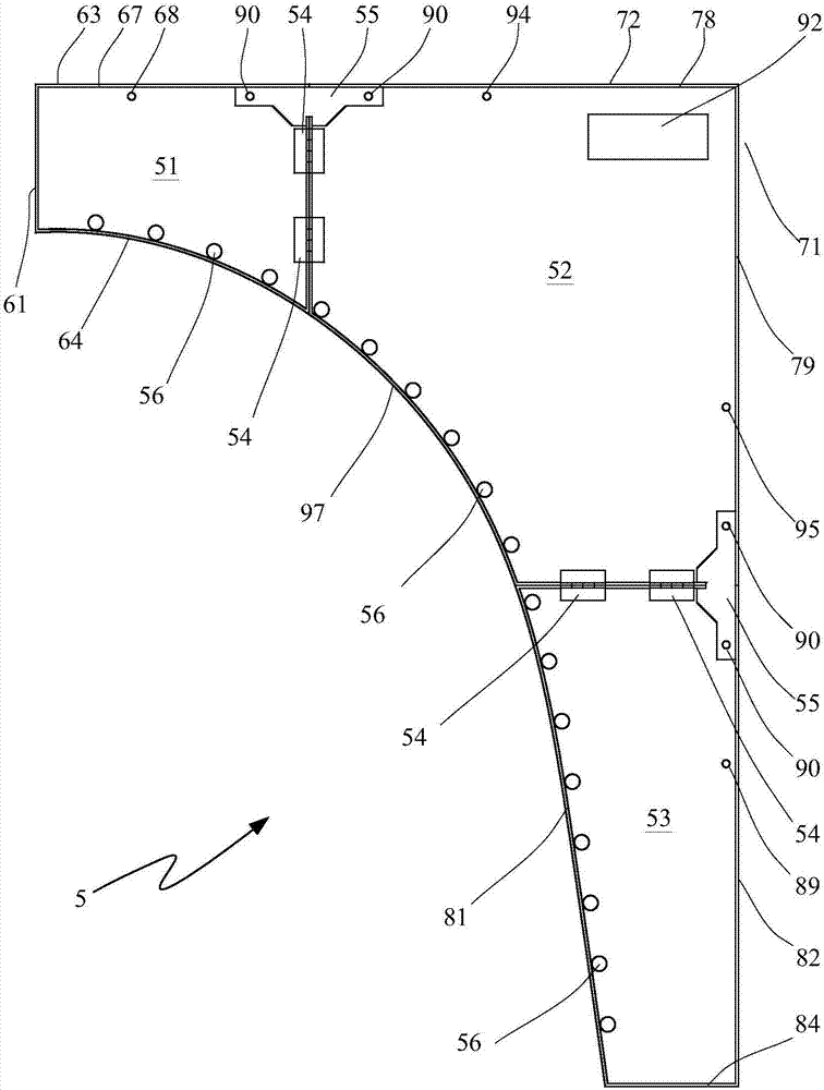
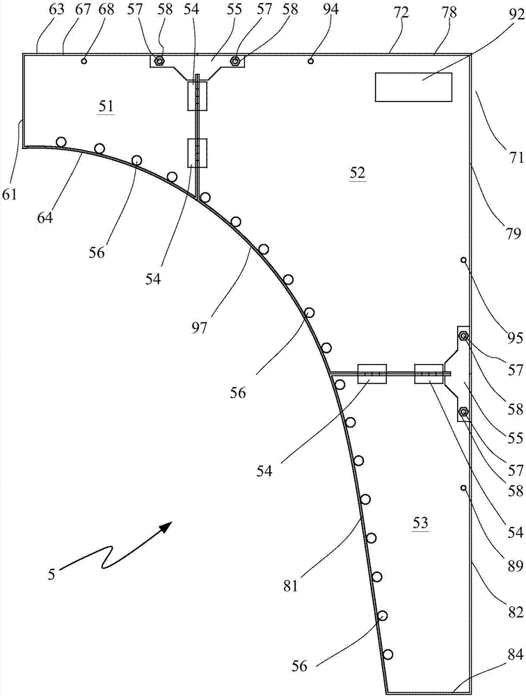
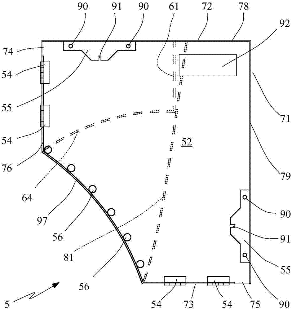
[0041]During use, the foldable positioning plate for the reamer generally has two states: unfolded and folded. For ease of description, components are sometimes described in relative terms such as inner, outer, upper, lower, front and rear, although these terms should not be regarded as essential. The inner side refers to the side closer to the axis of the reamer, and similarly, the outer side refers to the side away from the axis of the reamer. Unless otherwise stated, these relative terms should be combined with figure 1 The orientation of the components shown is to be understood.

[0042] A foldable positioning board for a reamer is characterized in that: the foldable positioning board for a reamer includes an inner board 51, a main board 52, a lower board 53, a hinge 54, a fixing board 55 and a checking board 56; the main board 52 and the inner board Plate 51 is connected by hinge 54, main board 52 and lower board 53 are connected by hinge 54; The fixed plate 55 is conn...


PUM


Abstract

The invention relates to a foldable positioning plate for a reamer, and belongs to the technical field of reamer positioning. According to the foldable positioning plate for the reamer, a main plate and an inner plate are connected through a hinge, and the main plate and a lower plate are connected through a hinge. When the positioning plate is unfolded, the main plate and the inner plate are connected through a fixing plate, and the main plate and the lower plate are connected through a fixing plate. When the positioning plate is folded, the inner plate is connected and attached to the main plate through the hinge, and the lower plate is connected and attached to the main plate through the hinge. The lower edge of the inner plate is provided with an arc boundary, a check plate is arranged, a distance is kept between the check plate and the arc boundary of the lower edge of the inner plate, and the boundary of the inner plate is provided with a rib plate. The main plate is provided with an arc positioning boundary, a check plate is arranged, a distance is kept between the check plate and the arc positioning boundary, and a rib plate is arranged on the boundary of the main plate. The inner edge of the lower plate is provided with an arc boundary, a check plate is arranged, a distance is kept between the check plate and the arc boundary of the inner edge of the lower plate, and the boundary of the lower plate is provided with a rib plate. The foldable positioning plate has the advantages that the structure is simple, on-site construction is achieved, disassembly and assembly are convenient, conveying is convenient, and the positioning precision is high.

Description

technical field [0001] The invention belongs to the technical field of reamer positioning, in particular to a foldable positioning plate for a reamer. Background technique [0002] At present, in the construction process of engineering ship machinery, the construction of cutter suction dredger occupies a pivotal position. When mechanical equipment such as reamers are in contact with earthwork, parts such as cutter teeth are severely worn and replaced frequently. These wearing parts are all installed on the mechanical equipment according to the designed spatial position, and the installation positioning accuracy has an important impact on the construction stability and working life of the construction machinery, and has a significant impact on the production efficiency. These easy-to-wear parts are not only worn by earth and rocks, but also bear strong impact loads. If the wear is severe, they need to be returned to the factory for repair or even scrapped directly. The direc...

Claims


Application Information

Patent Timeline
Patent Type & Authority Applications(China)
IPC IPC(8): E02F3/90
CPCE02F3/90
Inventor 苏召斌林森姜曦杨建华刘俸麟
Owner CCCC TIANJIN ECO ENVIRONMENTAL PROTECTION DESIGN & RES INST CO LTD
Why Eureka
Try Eureka