
A theoretical zero-error dynamometer

A dynamometer and zero-error technology, applied in the field of theoretical zero-error dynamometers, can solve problems such as high cost, failure to meet energy-saving requirements, severe heat generation, etc.

Inactive Publication Date: 2019-07-12
SHANDONG JIANZHU UNIV
View PDF8 Cites 0 Cited by
  • Summary
  • Abstract
  • Description
  • Claims
  • Application Information

AI Technical Summary

Problems solved by technology

Theoretically speaking, this error will always exist, although it can be made very small, it still exists
② Self-heating is very severe, so it must be equipped with special cooling components such as air cooling or water cooling
Therefore, the above types of dynamometers do not meet the current energy-saving requirements, and the structure is complex, the floor space is large, and the cost is high

Method used

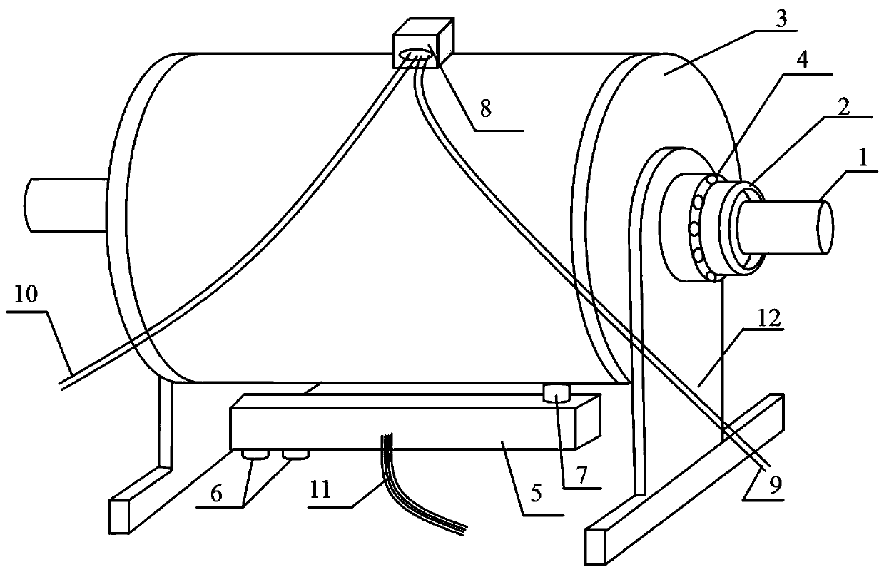
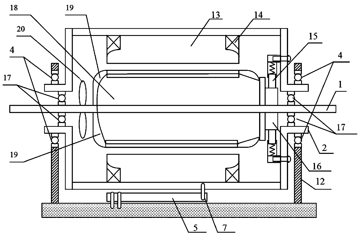

Image

  • A theoretical zero-error dynamometer
  • A theoretical zero-error dynamometer
  • A theoretical zero-error dynamometer

Examples


Embodiment Construction

[0016] The present invention will be further described below in conjunction with the drawings and embodiments.

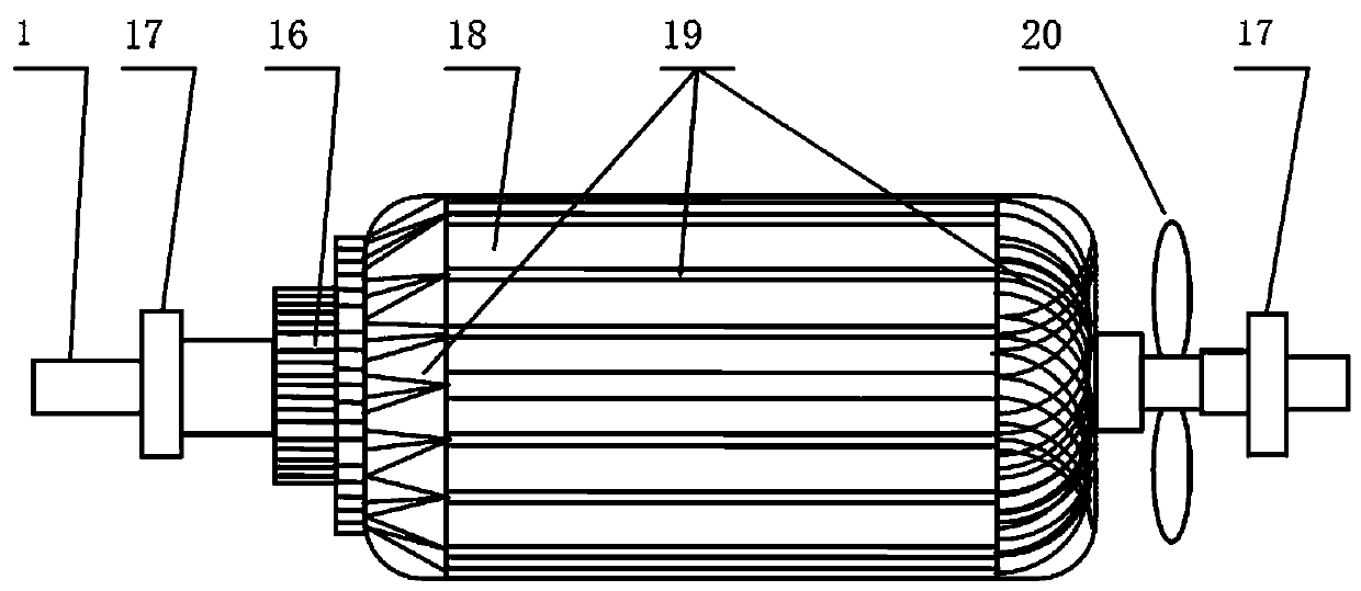
[0017] Such as figure 1 with figure 2 As shown, the three-dimensional view and the cross-sectional view of the theoretical zero-error dynamometer of the present invention are respectively given. The dynamometer shown consists of a rotor, a stator 13, a shaft 1, a housing 3, an end cover 2, a rotor bearing 17, and a housing bearing. 4. The supporting plate 12 and the force sensor 11 are composed. The rotor is composed of a rotor core 18 and a rotor winding 19, and the rotor core 18 is fixed on the rotating shaft 1 to realize the rotor core 18 to follow the rotating shaft 1 to rotate. The stator 13 shown is located on the periphery of the rotor. The stator 13 is provided with an excitation winding 14 and the stator 13 is specified to be able to be connected to the housing 3. Both ends of the rotating shaft 1 are fixed to the housing 3 through rotor bearings 17 to realize...


PUM


Abstract

A theoretical zero-error dynamometer comprises a shell, a stator, a rotor, a rotating shaft and a supporting plate, and is characterized in that both end surfaces of the shell are fixed with end cap sleeves; the end cap sleeves are fixed on the supporting plate by shell bearings; a force sensor is arranged below the shell; one end of the force sensor is fixed to a workbench or the ground through fixing screws; and the other end of the force sensor is fixed to the shell through a pin. According to the dynamometer of the invention, since the rotating shaft is fixed on the shell through a rotor bearing, nearly no energy losing occurs in a process that an output shaft of a tested motor drives the rotating shaft to rotate; and since the shell is fixed on the supporting plate through the shell bearings, nearly no frictional force exists between the shell (rotor) and the supporting plate, thus output signals of the force sensor can truly reflect an output torque of the tested motor and the measured value basically has no error.

Description

Technical field [0001] The invention relates to a theoretical zero-error dynamometer, and more specifically, to a theoretical zero-error dynamometer in which end cover sleeves at both ends of a dynamometer shell are fixed on a support plate through shell bearings. Background technique [0002] At present, common dynamometers include hysteresis dynamometer, magnetic particle dynamometer and eddy current dynamometer. These dynamometers have a common feature, ① they have static friction errors. In theory, this error will always exist. Although it can be made very small, it still exists. ②The self-heating is very strong, so it must be equipped with special cooling components such as air cooling or water cooling. The reason is that all the mechanical energy inside the dynamometer is converted into heat energy, which is all concentrated on the dynamometer itself. The phenomenon of dynamometer heating is especially obvious when working continuously for a long time. Therefore, the ab...

Claims


Application Information

Patent Timeline
Patent Type & Authority Patents(China)
IPC IPC(8): G01L3/24
CPCG01L3/24
Inventor 李全民罗珂
Owner SHANDONG JIANZHU UNIV
Learn More