Measurement device for measuring plate spring compressive force of fuel assembly

A technology for fuel assemblies and measuring devices, which is applied in measuring devices, force/torque/work measuring instruments, instruments, etc., and can solve problems such as inability to apply, complex structure of spring pressure testing machines, and inability to work underwater.

Active Publication Date: 2017-08-04
CHINA NUCLEAR POWER TECH RES INST CO LTD +3
View PDF11 Cites 3 Cited by
  • Summary
  • Abstract
  • Description
  • Claims
  • Application Information

AI Technical Summary

Problems solved by technology

The main machine part is composed of four columns, upper beams, middle beams, and workbench. The beam drives the tensile attachment to move up and down to realize the loading and unloading of the sample; the spring pressure testing machine with this structure is complex and cannot work underwater, so it cannot be applied to the fuel assembly in the spent fuel pool. The compression force (ie: elastic force) of the leaf spring of the upper tube seat is measured

Method used


Image

  • Measurement device for measuring plate spring compressive force of fuel assembly
  • Measurement device for measuring plate spring compressive force of fuel assembly
  • Measurement device for measuring plate spring compressive force of fuel assembly

Examples


Embodiment Construction

[0019] Embodiments of the present invention will now be described with reference to the drawings, in which like reference numerals represent like elements.

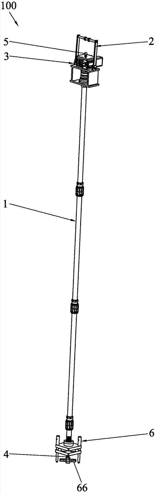
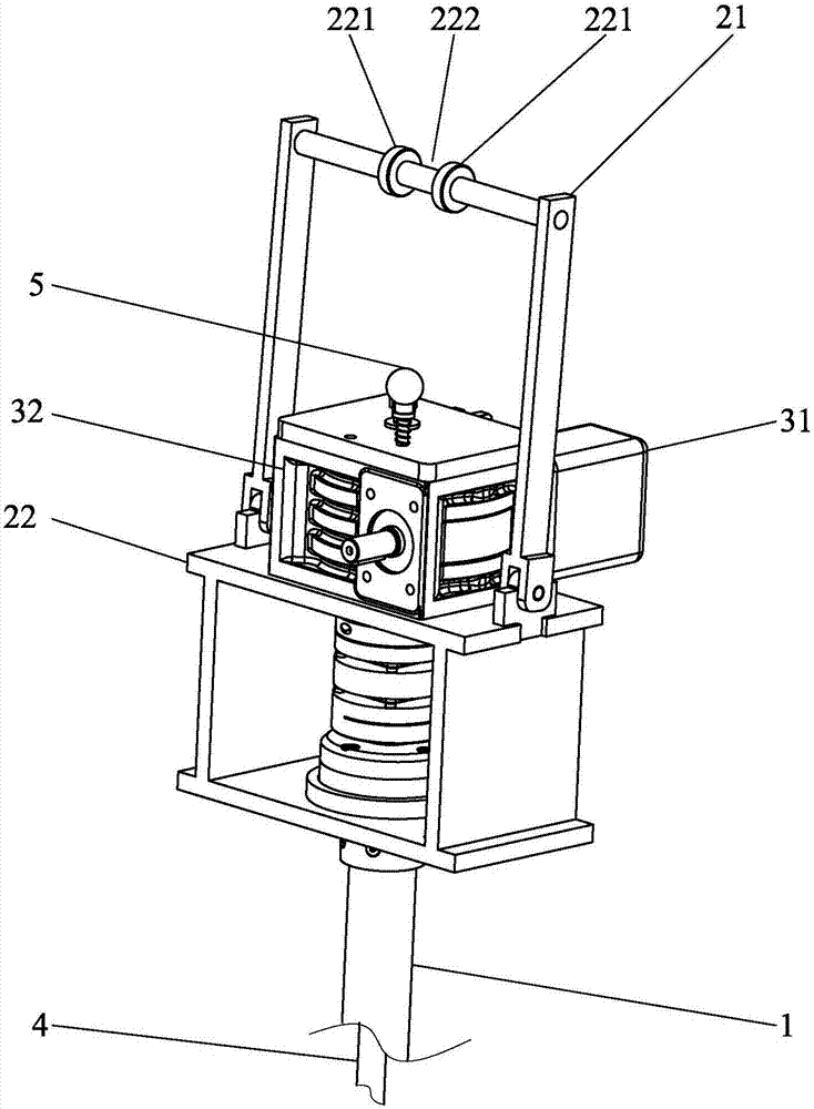
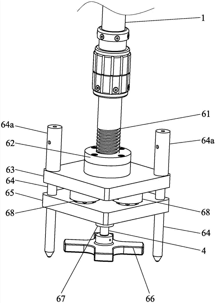
[0020] Such as Figure 1-Figure 4As shown, the fuel assembly leaf spring pressing force measuring device 100 of the present invention is used to measure the pressing force of the leaf spring in the upper tube seat of the fuel assembly. The fuel assembly leaf spring pressing force measuring device 100 includes an outer tube 1 , an upper supporting mechanism 2, a driving mechanism 3, a core rod 4, a handle 5 and a pressing force measuring mechanism 6, the outer tube 1 is a hollow structure, so that the outer tube of the present invention is a cylindrical structure; the upper supporting mechanism 2 includes Support base 21 and hanger 22, hanger 22 is arranged on the support base 21, and this hanger 22 is used for the hook of crane to hang, thereby the present invention is hoisted and moved; Driving mechanism 3 is arranged on...


PUM


Abstract

The present invention discloses a measurement device for measuring the plate spring compressive force of a fuel assembly. The device comprises an outer pipe, an upper support mechanism, a driving mechanism, a core rod and a compressive force measurement mechanism. The outer pipe is of a hollow structure. The upper support mechanism comprises a support seat and a hanging bracket. The driving mechanism is arranged on the support seat. The driving mechanism drives the outer pipe to rotate. The core rod is connected with a handle. The compressive force measurement mechanism comprises a screw rod, a screw rod nut, a mounting plate, a positioning pin, a pressing plate, a clamping plate, a pressure sensor and a display. The screw rod is in butt joint with the outer pipe. The screw rod nut is arranged on the mounting plate. The screw rod penetrates through the screw rod nut. The positioning pin is elastically connected with the mounting plate and penetrates through the pressing plate. The core rod penetrates through the outer pipe and the pressing plate to be detachably connected with the clamping plate. A shaft sleeve is arranged on the core rod to stop the pressing plate from sliding downwardly and vertically. The pressure sensor is arranged on the mounting plate to be electrically connected with the display. During the measurement process, a plate spring is clamped between the clamping plate and the pressing plate, so that the interference of external forces is avoided. The measurement device is accurate and reliable in measurement, and simple and practical in structure.

Description

technical field [0001] The invention relates to a measuring tool for a fuel assembly, in particular to a measuring device for measuring the compression force of a leaf spring in an upper pipe seat of a fuel assembly. Background technique [0002] The spring pressure testing machine adopts a double-space floor-standing structure, the upper space is stretched, and the lower space is compressed and bent. The host part is composed of four columns, upper beams, middle beams, and workbenches to form a floor-standing frame. The speed control system is installed at the lower part of the workbench. The AC servo motor drives the ball screw to rotate through the synchronous toothed belt deceleration system. The ball screw drives the The beam drives the tensile attachment to move up and down to realize the loading and unloading of the sample; the spring pressure testing machine with this structure is complex and cannot work underwater, so it cannot be applied to the fuel assembly in the...

Claims


Application Information

Patent Timeline
Patent Type & Authority Applications(China)
IPC IPC(8): G01L5/00
CPCG01L5/00Y02E30/30
Inventor 李晓鹿帅陈嘉杰吴玉殷勇徐宏伟吴梦莹黄海华刘帅孙飞翔
Owner CHINA NUCLEAR POWER TECH RES INST CO LTD
Why Eureka
Try Eureka