
Coupling coefficient detection circuit among magnetic coupling inductance coils and method thereof

A technology of inductance coils and coupling coefficients, which is applied in the field of detection of coupling coefficients between inductance coils, can solve the problems of complex detection methods, large errors, and non-unique calculation expressions, and achieve the effects of easy construction, low cost, and accurate numerical calculations

Active Publication Date: 2017-08-04
UNIV OF ELECTRONICS SCI & TECH OF CHINA
View PDF7 Cites 4 Cited by
  • Summary
  • Abstract
  • Description
  • Claims
  • Application Information

AI Technical Summary

Problems solved by technology

[0003] The purpose of the present invention is to provide a coupling coefficient detection circuit and method between magnetically coupled inductor coils for the existing magnetically coupled inductor coil coupling coefficient detection method is complicated, the calculation expression is not unique, and the error is relatively large; The technical solution is:

Method used


Image

  • Coupling coefficient detection circuit among magnetic coupling inductance coils and method thereof
  • Coupling coefficient detection circuit among magnetic coupling inductance coils and method thereof
  • Coupling coefficient detection circuit among magnetic coupling inductance coils and method thereof

Examples


Embodiment Construction

[0021] The present invention will be described in detail below in conjunction with the accompanying drawings and embodiments.

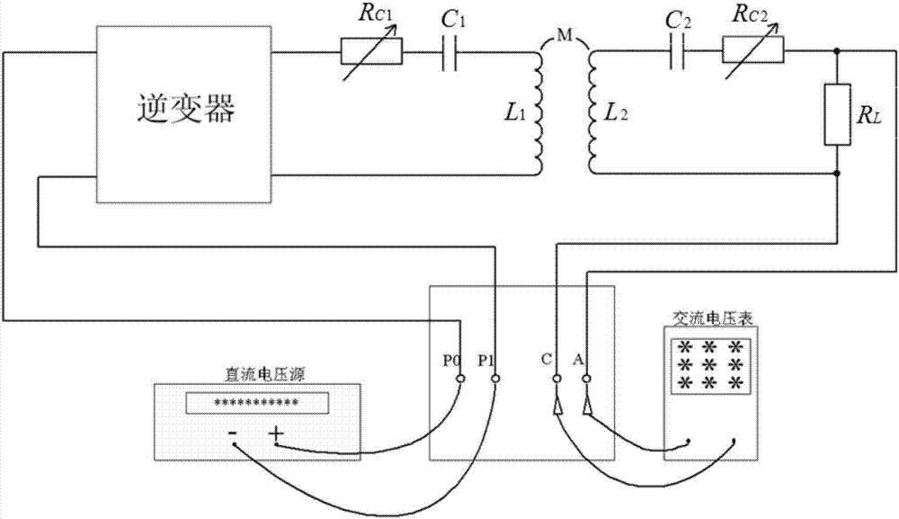
[0022] In this embodiment, the coupling coefficient detection circuit between the magnetically coupled inductance coils, its principle is as follows figure 1 As shown, its circuit connection diagram is shown in figure 2 shown; including DC voltage supply, inverter, primary series capacitor C 1 , Primary variable trimming resistor R C1 , primary inductance coil L 1 , Secondary inductance coil L 2 , Secondary series capacitor C 2 , Secondary variable trimming resistor R C2 and sense resistor R L ; It is characterized in that the DC voltage power supply is connected to the two input terminals P of the inverter 0 ,P 1 , the primary variable trimmer resistor R C1 , primary series capacitor C 1 with the primary inductance coil L 1 The two output terminals of the inverter are connected in sequence to form a primary resonant circuit; the secondary...


PUM


Abstract

The invention belongs to the coupling coefficient detection technology field among inductance coils and provides a coupling coefficient detection circuit among magnetic coupling inductance coils and a method thereof. The circuit and the method are used to overcome defects that an existing detection method is complex; a calculating expression is not unique and an error is large. The detection circuit comprises a direct voltage power supply, an inverter, a primary series capacitor, a primary variable trimming resistor, a primary inductance coil, a secondary inductance coil, a secondary series capacitor, a secondary variable trimming resistor and a detection resistor. The direct voltage power supply is connected to two input terminals of the inverter. The primary variable trimming resistor, the primary series capacitor and the primary inductance coil are successively connected and then are connected to two output terminals of the inverter so as to form a primary resonance loop. The secondary inductance coil, the secondary series capacitor, the secondary variable trimming resistor and the detection resistor are successively connected so as to form a secondary resonance loop. The detection circuit is simple and is convenient for constructing. An analytical expression of a coupling coefficient is accurate and high-efficient.

Description

technical field [0001] The invention belongs to the technical field of coupling coefficient detection between inductance coils, and relates to a coupling coefficient detection circuit and method for magnetically coupled inductance coils. Background technique [0002] The detection of the coupling coefficient between the existing magnetically coupled inductor coils is usually expressed by a numerical expression, and the numerical solution of the coupling coefficient is obtained. First, the integral formula of the mutual inductance coefficient is derived by using the Biot-Savart law, and then the numerical calculation is performed. Analyze the situation and guess the non-extreme situation, use power series, exponent, logarithm or their combination to test, and then use numerical calculation to verify, and finally try to deduce that the two coils are at any distance (except that the two inductance coils are almost Approximate analytical expressions for mutual inductance and cou...

Claims


Application Information

Patent Timeline
Patent Type & Authority Applications(China)
IPC IPC(8): G01R33/12
CPCG01R33/12
Inventor 王京梅赵文俊林晓明董岳
Owner UNIV OF ELECTRONICS SCI & TECH OF CHINA
Learn More