Near-to-eye binocular display device

A display device and binocular technology, applied in optical components, optics, instruments, etc., to achieve the effect of large exit pupil near-eye binocular display

Active Publication Date: 2017-08-04
SOUTHEAST UNIV
View PDF9 Cites 12 Cited by
  • Summary
  • Abstract
  • Description
  • Claims
  • Application Information

AI Technical Summary

Problems solved by technology

[0003] Technical problem: The technical problem to be solved by the present invention is how to provide a near-eye binocular display device with high

Method used


Image

  • Near-to-eye binocular display device
  • Near-to-eye binocular display device
  • Near-to-eye binocular display device

Examples


Embodiment 1

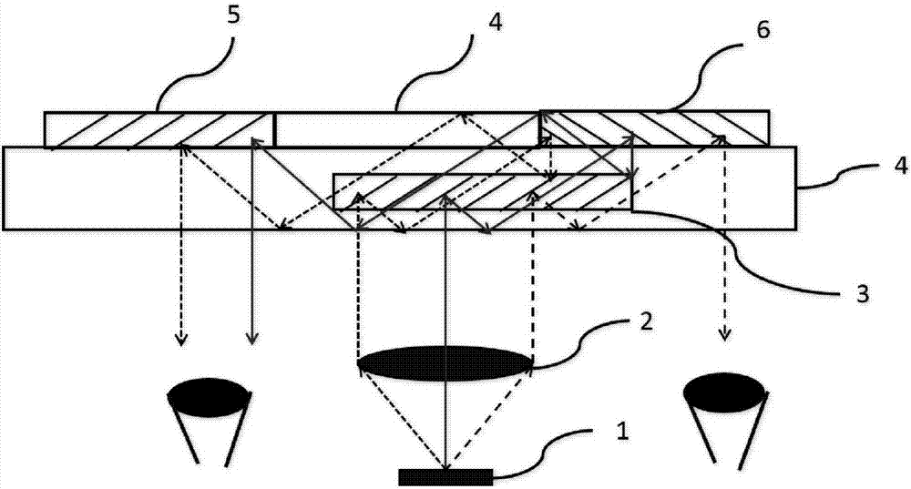
[0038] In embodiment 1, such as figure 2 As shown, the microdisplay 1 is used to emit a light beam containing two-dimensional image information, the light beam has a certain divergence angle, and becomes a parallel light beam after being collimated by the doublet lens 2, and the parallel light beam enters the waveguide 4 inside The reflective holographic grating 3 at the input end is coupled into the waveguide 4 for total reflection, and reaches the reflective holographic grating 5 at the output end. Part of the light undergoes Bragg diffraction and is coupled into the right eye of the observer; the other part of the light is diffracted and returns to the reflective input end. The holographic grating 3 undergoes the second Bragg diffraction, and the light beam propagates through total reflection to the left in the waveguide 4, and finally reaches the output holographic grating 6 located on the upper surface of the waveguide 4, and the output holographic grating 6 diffracts the...

Embodiment 2

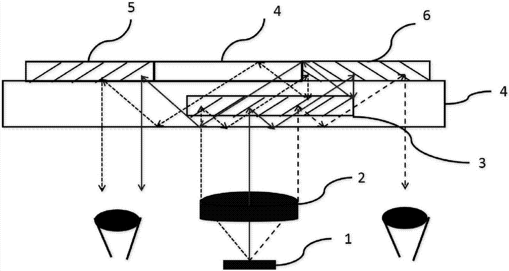
[0039] In embodiment 2, such as image 3 As shown, the microdisplay 1 is used to emit light beams containing two-dimensional image information. The light beams have a certain divergence angle and become parallel light beams after being collimated by the collimating lens group 2. The parallel light beams enter the waveguide 4 Inside the input end reflective holographic grating 3, a part of the light is coupled into the waveguide 4 for two total reflections, and reaches the output end holographic grating 6 located on the lower surface of the waveguide 4 to undergo Bragg diffraction, and the holographic grating 7 couples the light beam into the observer Right eye; another part of the light undergoes a total reflection in the waveguide 4, reaches the input end reflective holographic grating 5 located on the upper surface of the waveguide, and is diffracted back to the input end reflective holographic grating 3 for the second Bragg diffraction. Total reflection propagates to the le...

Embodiment 3

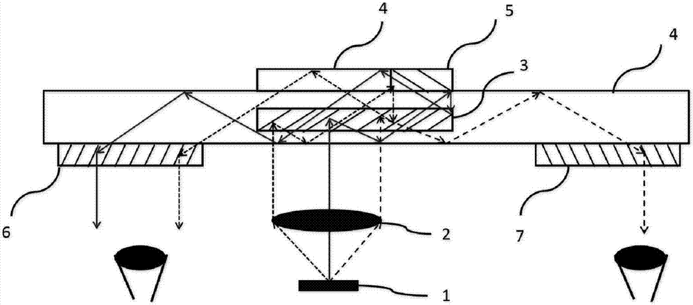
[0040] In embodiment 3, such as Figure 4 As shown, the input holographic grating 3 is a transmission holographic grating located on the lower surface of the input end of the waveguide 4 , and the input holographic grating 5 is a reflective holographic grating located inside the input end of the waveguide 4 . Both the output holographic grating 6 and the holographic grating 7 are transmission holographic gratings, which are located on the lower surface of the output end of the waveguide 4 .

[0041] The working principle in embodiment 3 is the same as that in embodiment 1 and embodiment 2, so it will not be repeated here.

[0042] The near-eye binocular display device of the above embodiment has the effect of single input and double output.

[0043] In the above embodiments, the reflective or transmissive holographic grating is not fixed, which needs to be determined in conjunction with the position of the microdisplay 1 and the holographic grating in the waveguide.


PUM

PropertyMeasurementUnit
Thicknessaaaaaaaaaa
Thicknessaaaaaaaaaa

Abstract

The invention relates to a near-eye binocular display device. The near-eye binocular display device is characterized in that the near-eye binocular display device comprises a micro-display (1), a collimating lens (2), a waveguide (4), an input end holographic grating (3), a left output end holographic grating (5) and an output end holographic grating (6); the micro-display (1) is located below the lower surface of the waveguide (4); the input end holographic grating (3) is located inside or on the surface of the waveguide (4); the left output end holographic grating (5) and the output end holographic grating (6) are located inside or on the surface of the waveguide (4); and the collimating lens (2) is located between the micro-display (1) and the waveguide (4) or on the lower surface of the waveguide (4). The holographic grating-waveguide structure of the near-eye binocular display device can evenly divide an original beam emitted by the micro-display into two beams; and the two beams are diffracted through the two output end holographic gratings respectively so as to enter the left eye and right eye of a user, and therefore, binocular display can be realized.

Description

technical field [0001] The invention relates to a head-mounted display device, which uses a waveguide system to transmit images in front of the wearer's eyes to realize the application of augmented reality. Background technique [0002] At present, the near-eye display devices (GOOGLE GLASS, etc.) on the market have a single-input and single-output structure, and most of them can only realize monocular display, while near-eye display devices that can realize binocular (SONY SED-E1, HOLOLENS, etc.) are dual-input and double-output structure, two sets of micro-display devices are required to provide left and right binocular images respectively, and the production cost of this solution is high, and the weight of the near-eye display device is greatly increased. Therefore, how to solve a single microdisplay device to realize near-eye binocular display has become a technical problem to be solved. Contents of the invention [0003] Technical problem: The technical problem to be...

Claims


Application Information

Patent Timeline
IPC IPC(8): G02B27/01
CPCG02B27/0172G02B2027/0174
Inventor 张宇宁沈忠文刘奡翁一士
Owner SOUTHEAST UNIV
Why Eureka
Try Eureka