
Laser resistance trimming method and device, laser resistance trimming system

A laser resistance trimming and laser technology, applied in resistors, resistance manufacturing, electrical components, etc., can solve problems such as resistance deviation

Active Publication Date: 2018-09-11
SHENZHEN JPT OPTO ELECTRONICS CO LTD
View PDF6 Cites 0 Cited by
  • Summary
  • Abstract
  • Description
  • Claims
  • Application Information

AI Technical Summary

Problems solved by technology

The power frequency interference will cause the deviation of the measured value of the resistance value of the resistance when measuring the resistance value of the resistance, and the deviation of the correction will be generated when the resistance value of the laser is corrected

Method used


Image

  • Laser resistance trimming method and device, laser resistance trimming system
  • Laser resistance trimming method and device, laser resistance trimming system
  • Laser resistance trimming method and device, laser resistance trimming system

Examples


Embodiment Construction

[0019] In order to make the object, technical solution and advantages of the present invention clearer, the present invention will be further described in detail below in conjunction with the accompanying drawings and embodiments. It should be understood that the specific embodiments described here are only used to explain the present invention, not to limit the present invention.

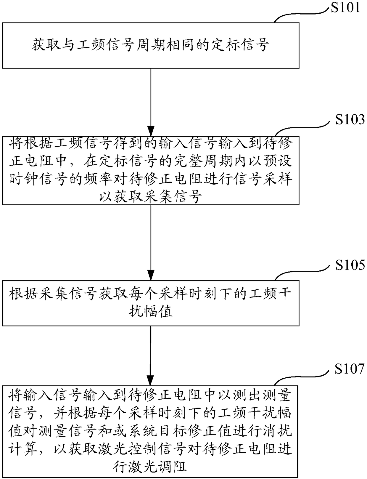
[0020] like figure 1 shown. A laser resistance adjustment method can suppress the interference of power frequency signals when the resistance value of the resistance to be corrected is corrected. The laser trimming method includes:

[0021] S101. Acquire a calibration signal with the same period as the power frequency signal.

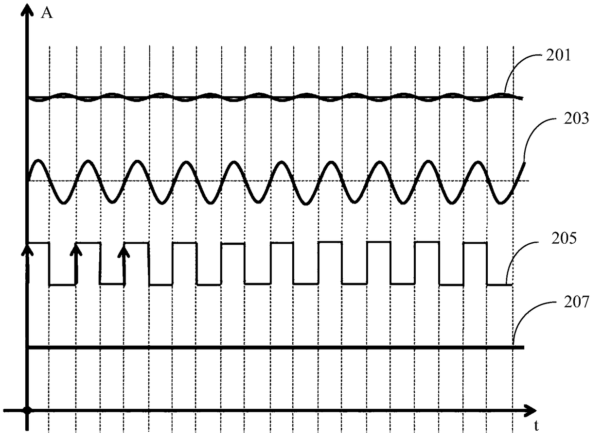
[0022] In this embodiment, the power frequency signal of the system equipment is passed through the zero-crossing detection module, so as to obtain the required calibration signal. The calibration signal is a square wave signal with the same period as the power frequency...


PUM


Abstract

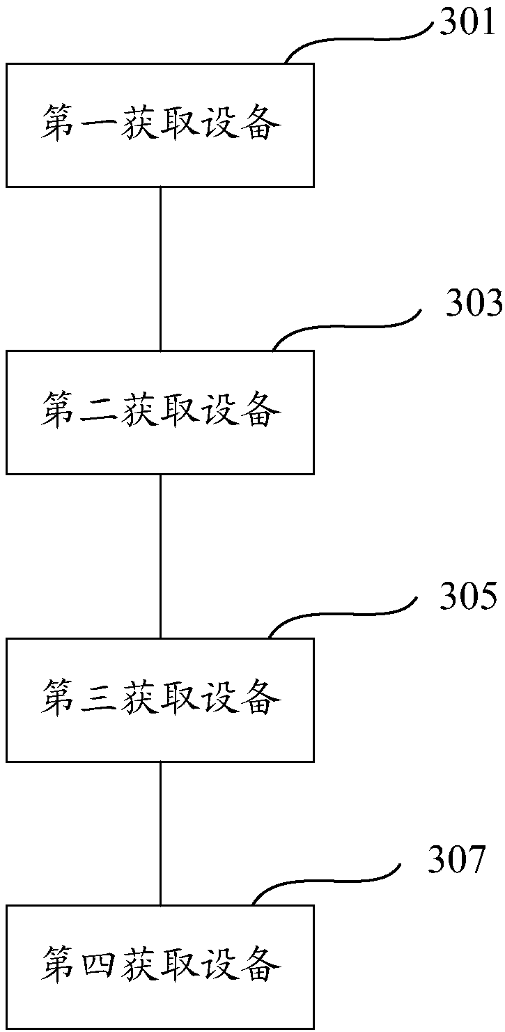
The invention relates to a laser resistor trimming method and device and a laser resistor trimming system. The laser resistor trimming method comprises the following steps: acquiring a calibration signal having the period identical with that of a power frequency signal; inputting an input signal, obtained according to the power frequency signal, into a to-be-corrected resistor, and performing signal sampling onto the to-be-corrected resistor within the complete period of the calibration signal at the preset clock signal frequency, so as to acquire a collection signal; according to the collection signal, acquiring the power frequency interference amplitude value at each sampling moment; inputting the input signal into the to-be-corrected resistor so as to measure the measurement signal, and conducting interference cancellation calculation onto the measurement signal and / or the system target correction value according to the power frequency interference amplitude value at each sampling moment, so as to acquire a laser control signal for conducting laser resistor trimming onto the to-be-corrected resistor. According to the laser resistor trimming method, when the to-be-corrected resistor is subjected to laser resistor trimming, the power frequency interference amplitude value is referenced, and the power frequency interference can be inhibited, so that the resistance measurement precision of the to-be-corrected resistor can be increased.

Description

technical field [0001] The invention relates to the technical field of laser resistance adjustment, in particular to a method and device for laser resistance adjustment, and a laser resistance adjustment system. Background technique [0002] In actual production applications, when the traditional laser trimming machine corrects the resistance value of thick and thin film resistors, the power frequency interference of the mains will crosstalk into the measurement module of the system. The power frequency interference will cause the deviation of the resistance measurement value of the resistance when measuring the resistance value of the resistance, and the correction deviation will be generated when the resistance value of the resistance is corrected by laser. Therefore, the power frequency interference affects the precision measurement of the resistor and the SD (Standard Deviation, standard deviation) value of the resistor as a whole. Contents of the invention [0003] B...

Claims


Application Information

Patent Timeline
Patent Type & Authority Patents(China)
IPC IPC(8): H01C17/242
CPCH01C17/242
Inventor 许镇辉吴继东
Owner SHENZHEN JPT OPTO ELECTRONICS CO LTD
Learn More