Parameter measuring circuit and method for vibrating wire sensors
A vibrating wire sensor and parameter measurement technology, which is applied in the direction of using electric/magnetic devices to transmit sensing components, etc., can solve problems such as data jitter and affect data accuracy, achieve low power consumption, improve measurement accuracy, and prevent measurement errors Effect
- Summary
- Abstract
- Description
- Claims
- Application Information
AI Technical Summary
Problems solved by technology
Method used
Image
Examples
Embodiment 1
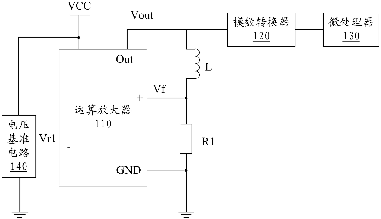
[0031] Please refer to figure 1 The present embodiment 1 provides a resistance measurement circuit of a vibrating wire sensor, including an operational amplifier 110, and an exciting coil L of a vibrating wire sensor is connected between the output terminal of the operational amplifier 110 and the non-inverting input terminal, wherein the excitation The resistance of the vibrating coil L is R L It means that the first resistor R1 is connected between the non-inverting input terminal of the operational amplifier 110 and the ground GND, the inverting input terminal of the operational amplifier 110 is connected with the first reference voltage signal Vr1, and the output terminal of the operational amplifier 110 A microprocessor 130 is also connected via an analog-to-digital converter 120 . The microprocessor 130 may be a single chip microcomputer (MCU), a digital signal processor (DSP), a complex programmable logic device (CPLD) or a field programmable gate array (FPGA). Where...
Embodiment 2
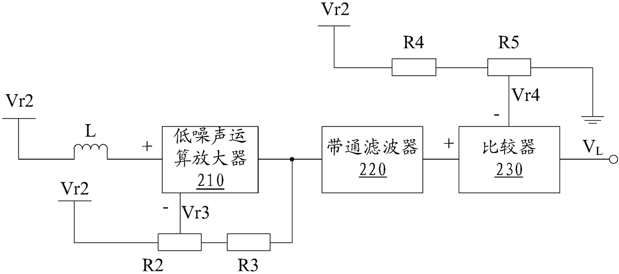
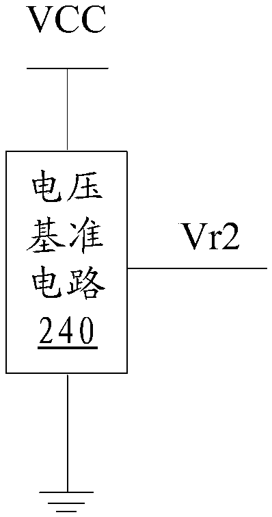
[0040] Please refer to figure 2 , the second embodiment provides a frequency measurement circuit for a vibrating wire sensor, including a second reference voltage signal Vr2, a low-noise operational amplifier 210 and a comparator 230, the second reference voltage signal Vr2 and the low-noise operational amplifier 210 The exciting coil L of the vibrating wire sensor is connected between the non-inverting input ends, the inverting input end of the low-noise operational amplifier 210 is connected with the third reference voltage signal Vr3, the output end of the low-noise operational amplifier 210 is connected to the A bandpass filter 220 is connected between the non-inverting input terminals of the comparator 230, the fourth reference voltage signal Vr4 is connected to the inverting input terminal of the comparator 230, and the output terminal of the comparator 230 is a vibrating wire sensor The digital level signal of the exciting coil L of the vibrating wire sensor is calcula...
PUM
 Abstract
Description
Claims
Application Information
 - R&D
- Intellectual Property
- Life Sciences
- Materials
- Tech Scout
- Unparalleled Data Quality
- Higher Quality Content
- 60% Fewer Hallucinations
Browse by: Latest US Patents, China's latest patents, Technical Efficacy Thesaurus, Application Domain, Technology Topic, Popular Technical Reports.
© 2025 PatSnap. All rights reserved.Legal|Privacy policy|Modern Slavery Act Transparency Statement|Sitemap|About US| Contact US: help@patsnap.com


