
Eureka
For R&D, Eureka makes reading and utilizing patents & technical documents easy.
Eureka AIR
Designed for self-driven R&D workflows. Generate viable solutions, solve complex R&D challenges, empower your innovation with AI.

Eureka Materials
Designed for material experts only. Revolutionize your material R&D, from search, analyze, to developing new materials.

TechResearch
Generate reliable direction feasibility study reports for your R&D in just a few steps.

TechSeek
Discover and master advanced knowledge NOW. Basics, ideas, possibilities, all at once.

TechMind
As an expert in R&D Theories, TechMind can generates customized viable solutions instantly.

TechRisk
Analyze your overall solution with one click, know your potential R&D risks in advance.

TechMonitor
Get weekly tech updates, stay abreast of the latest tech innovations and key insights.
Ultrasonic cleaner and substrate processing system
A technology for a substrate processing system and cleaning device, which is applied in the directions of cleaning flexible articles, cleaning methods and utensils, and cleaning methods using gas flow, etc., can solve problems such as affecting product quality, and achieve the effect of avoiding defects and reducing poor substrate treatment
- Summary
- Abstract
- Description
- Claims
- Application Information
AI Technical Summary
Problems solved by technology
Method used
Image

Examples
Embodiment 1
[0058] refer to Figure 4 As shown, since the opening or closing of the door 21 of the load lock chamber is performed by the air supply cylinder 23, the gas is usually discharged directly after the door 21 is opened and closed, and there is a problem of gas waste. Embodiment 1 of the present invention adds a recovery device at the tail end of the drive cylinder 22 according to this phenomenon, filters the gas exhausted in the cylinder through a filter (Filter) and then applies it to an ultrasonic cleaning device, thereby achieving the effect of recycling. The schematic diagram of gas recycling is shown in Figure 5, and the specific structure is as follows Figure 6 Shown: wherein, the gas supply cylinder 23 is also communicated with the blowing unit of the ultrasonic cleaning device 10, and is used to provide gas to the blowing unit, that is, the gas supply end 111 in the blowing unit 11 shares the gas supply cylinder 23 of the processing device 20; the above The processing d...
Embodiment 2
[0064]The original CDA (Clean Dry Air, clean and dry compressed air) air supply system of the production line can be used, and another pipeline can be connected to directly act on the above-mentioned ultrasonic cleaning device 10 set on the top of the door 21 of the load lock chamber .
[0065] The concrete operation process of ultrasonic cleaning device 10 and door 21 is as follows:
[0066] After the door 21 is issued an order to open, the ultrasonic cleaning starts to work;
[0067] In the process of conveying the glass substrate into the door 21 by the robot arm, the surface to be treated (usually the upper surface away from the robot arm) is continuously purged by the ultrasonic cleaning device 10, so as to achieve the cleaning effect. Effect.
Embodiment 3
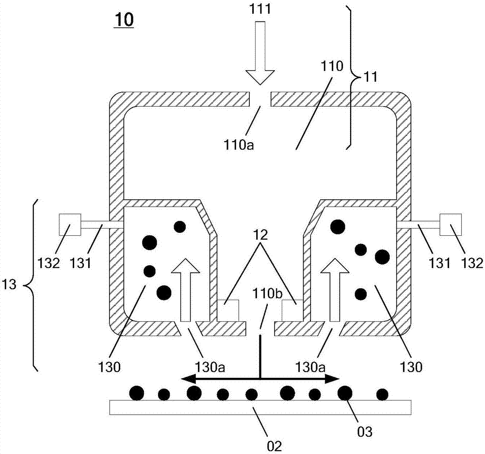
[0069] The gas supply end 111 of the air blowing unit 11 in the ultrasonic cleaning device 10 is specifically a negative pressure device connected to the atmosphere, so as to supply air to the pressure chamber 110 .
[0070] That is, a negative pressure device is installed to directly communicate with the atmosphere, so as to provide gas to the ultrasonic cleaning device 10 . The concrete operation process of ultrasonic cleaning device 10 and door 21 is as follows:
[0071] After the door 21 is issued an order to open, the ultrasonic cleaning starts to work;
[0072] In the process of conveying the glass substrate into the door 21 by the robot arm, the surface to be treated (usually the upper surface away from the robot arm) is continuously purged by the ultrasonic cleaning device 10, so as to achieve the cleaning effect. Effect.
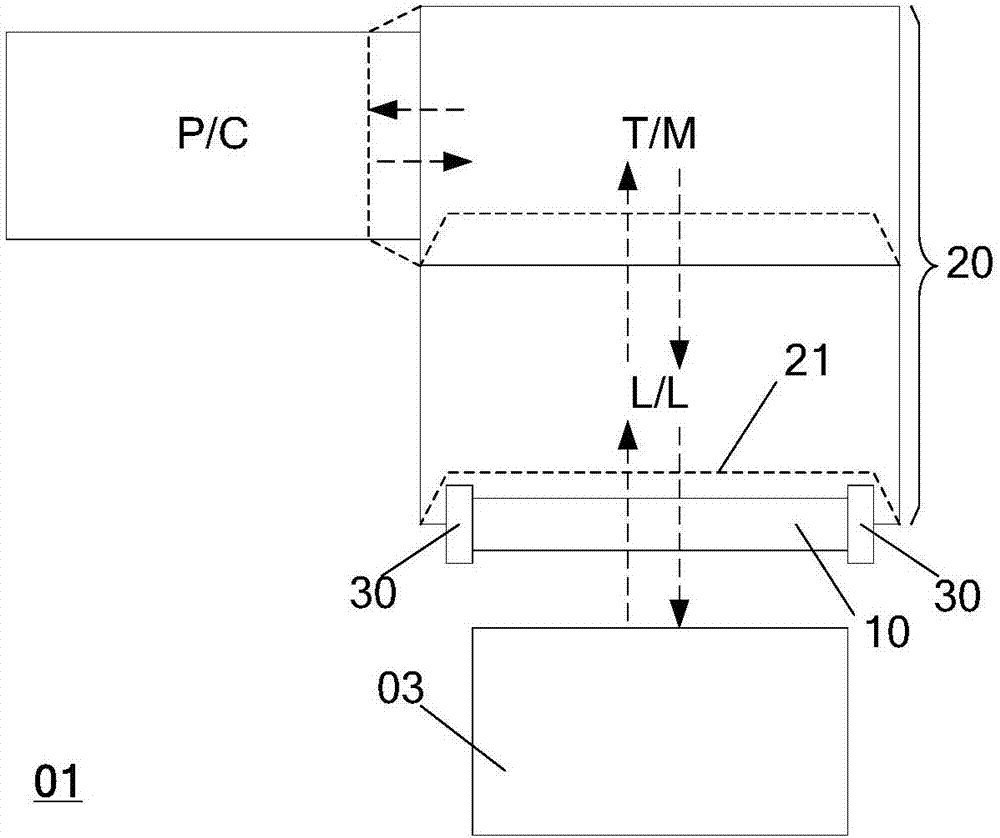
[0073] On the basis of the above, refer to image 3 As shown, the entrance 21 of the above-mentioned processing device 20 is also provided with ...
PUM
 Abstract
Description
Claims
Application Information
 - R&D Engineer
- R&D Manager
- IP Professional
- Industry Leading Data Capabilities
- Powerful AI technology
- Patent DNA Extraction
Browse by: Latest US Patents, China's latest patents, Technical Efficacy Thesaurus, Application Domain, Technology Topic, Popular Technical Reports.
© 2024 PatSnap. All rights reserved.Legal|Privacy policy|Modern Slavery Act Transparency Statement|Sitemap|About US| Contact US: help@patsnap.com