Pipe type air guiding device with damping for air compressor rotor

A compressor rotor and damping tube technology, which is applied to the air inlet of the turbine/propulsion unit, combustion air/combustion-air treatment, charging system, etc., can solve problems such as reduced reliability, vibration problems, and heavy structural weight. , to improve reliability and life, save assembly time, and facilitate later maintenance.

Active Publication Date: 2017-08-08
AECC SHENYANG ENGINE RES INST
View PDF6 Cites 15 Cited by
  • Summary
  • Abstract
  • Description
  • Claims
  • Application Information

AI Technical Summary

Problems solved by technology

[0004] 1. The air induction pipe has not taken proper vibration reduction measures. As a rotor part, it will inevitably cause vibration problems during the rotation of the compressor rotor. If the vibration cannot be effectively controlled, it may cause damage to itself and reduce reliability;
[0005] 2. The volume of the air-entraining disc body is large, which makes its structure heavy, which is not conducive to reducing the weight of the air-entraining device, and the radius of the air-entraining disc body is relatively large, making its rotation radius large, resulting in During the process, its own stress is relatively large

Method used


Image

  • Pipe type air guiding device with damping for air compressor rotor
  • Pipe type air guiding device with damping for air compressor rotor
  • Pipe type air guiding device with damping for air compressor rotor

Examples


specific Embodiment

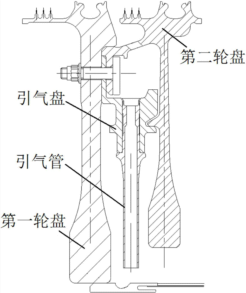
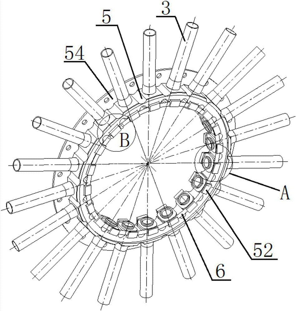
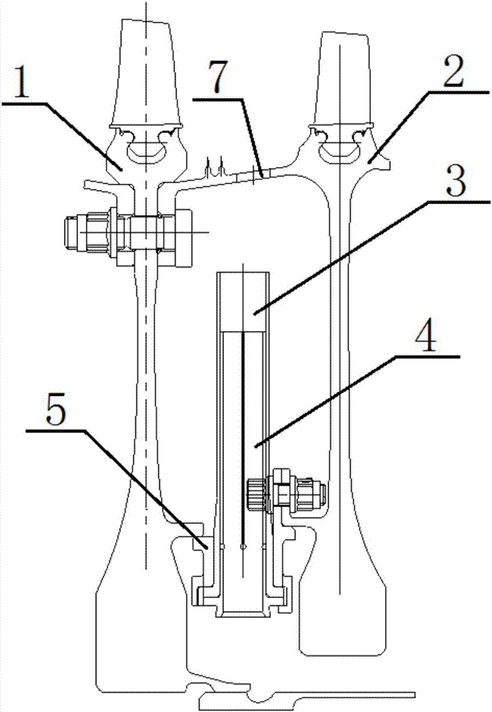
[0041] Such as figure 2 and image 3 As shown, the present invention provides a tube-type compressor rotor air-inducing device with damping, which is used to guide the air flow from the hub of the compressor to the hub, and the air-inducing device is installed and fixed on the first Between the disc 1 and the second disc 2, the air-inducing device includes an air-inducing pipe 3, a damping pipe 4 and an air-inducing disc 5;

[0042] The structure of the bleed pipe 3 is as Figure 4 and Figure 5 As shown, the bottom of the pipe wall of the air induction pipe 3 is provided with an air induction pipe flanging 31, and the structure of the damping pipe 4 is as follows: Image 6 and Figure 7 As shown, the tube wall of the damping tube 4 is coaxially provided with a damping tube protrusion 41. In the present embodiment, the flange 31 of the air-inducing tube and the protrusion 41 of the damping tube are all rectangular with rounded corners, and the flange 31 and the flange of ...


PUM


Abstract

The invention relates to the technical field of structural design of an air compressor rotor, and particularly provides a pipe type air guiding device with damping for the air compressor rotor. The air guiding device is used for guiding air flow to flow from a hub of an air compressor to a disc center and comprises air guiding pipes, damping pipes and an air guiding disc; the pipe walls of the air guiding pipes are provided with air guiding pipe flanges, the pipe walls of the damping pipes are provided with damping pipe protrusions, the top surfaces of the air guiding pipe flanges are in contact with the air guiding disc, and the bottom surfaces of the air guiding pipe flanges are in fit contact with the top surfaces of the damping pipe protrusions; the air guiding disc is a hollow disc, pipe holes for installing the air guiding pipes are formed in the outer wall of the air guiding disc, sleeve part fixing blocks used for fixing the air guiding pipes on the pipe holes axially are arranged on the end surface of one side of the air guiding disc, and stop blocks protruding out from the end surface of the other side of the air guiding disc are arranged on the end surface of the other side of the air guiding disc; the air guiding disc is provided with a clamping ring, the end surfaces of the two sides of the clamping ring make contact with the stop blocks and the air guiding pipe flanges respectively, and the air guiding pipes are fixed on the air guiding disc circumferentially by the clamping ring; and the clamping ring is provided with clamping ring heads protruding out from the end surface of the clamping ring, and the clamping ring heads are matched with the stop blocks to enable the clamping ring to be fixed in the circumferential direction of the air guiding disc.

Description

technical field [0001] The invention relates to the technical field of compressor rotor structure design, in particular to a tube-type compressor rotor air-inducing device with damping. Background technique [0002] When the aero-engine is working, it needs to bleed air from the compressor rotor part to seal or cool other parts. Due to the high speed of the compressor rotor part, the gas enters a typical rotating disc cavity, and the radial inflow process will A strong vortex is formed. If the gas forms a free vortex, the swirl flow formed during the radial inward flow will become more and more intense, resulting in a very large pressure loss, which can be well solved by designing a vortex reducer in the air-bleed device question. [0003] The vortex reducers used at this stage mainly include tube type, nozzle type, plate type and so on. Such as figure 1 As shown, the tubular vortex reducer is a series of radial circular tubes installed between the compressor discs, thro...

Claims


Application Information

Patent Timeline
Patent Type & Authority Applications(China)
IPC IPC(8): F02C7/04
CPCF02C7/04
Inventor 袁森印雪梅葛长闯孙浩然张岩张海洋
Owner AECC SHENYANG ENGINE RES INST
Why Eureka
Try Eureka