Heat induction defect detection method and system

A defect detection and heating technology, applied in the field of data processing, to achieve the effect of accurate and reliable judgment and accurate detection results

Active Publication Date: 2017-08-08
SHENZHEN LAUNCH DIGITAL TECH +1
View PDF14 Cites 11 Cited by
  • Summary
  • Abstract
  • Description
  • Claims
  • Application Information

AI Technical Summary

Problems solved by technology

[0005] In view of this, the present invention provides a thermal defect detection method and system to solve the p

Method used


Image

  • Heat induction defect detection method and system
  • Heat induction defect detection method and system
  • Heat induction defect detection method and system

Examples


Example Embodiment

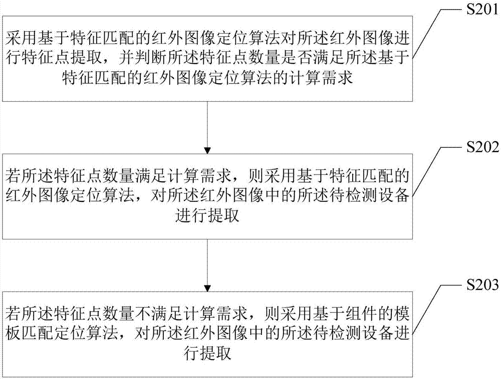
[0041] As a specific embodiment 2 of extracting the image of the device to be detected in the infrared image in step S101, including:

[0042] Step S201, using the infrared image positioning algorithm based on feature matching to extract feature points from the infrared image, and judging whether the number of feature points meets the calculation requirements of the infrared image positioning algorithm based on feature matching.

[0043] The infrared image positioning algorithm based on feature matching in this embodiment mainly includes a feature point collection part, a feature point matching part and a similarity judgment part, wherein the Surf algorithm is used as the algorithm of the feature point collection part. Since the Surf algorithm is a prior art, Not described in detail in this manual. For the feature point matching part, it is mainly used to judge whether the feature points collected in the infrared image have corresponding matching feature points in the referenc...

Example Embodiment

[0049] As another preferred specific embodiment 3 of step S102, it also includes:

[0050] If the type of equipment is non-multi-phase operation equipment, and the type of heating defect is voltage heating type, select the line segment area of ​​the heating part in the equipment to be tested, and analyze the comprehensive curve dispersion defect judgment method and the similar temperature rise comparison judgment method, as a thermal defect analysis method. When it is identified that the equipment to be tested is not a multi-phase operation equipment and is a voltage-induced heating type equipment, in this embodiment, preferably, the line segment area is selected as the heating analysis area of ​​the equipment to be tested, and the curve dispersion defect judgment method and similar methods are used. The comprehensive analysis of the temperature rise comparison judgment method is used as the analysis method of thermal defects, and the specific steps are as follows:

[0051] S...

Example Embodiment

[0055] As another preferred specific embodiment 4 of step S102, it also includes:

[0056] If the equipment type is multi-phase operation equipment, and the heating defect type is voltage heating type, select the line segment area of ​​the heating part in the equipment to be tested, and comprehensively curve dispersion defect judgment method, curve similarity judgment method and similar temperature rise comparison The judgment method is used as the analysis method for thermal defects. The detailed steps are as follows:

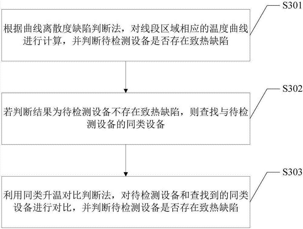
[0057]Step S401, according to the curve dispersion defect judgment method, calculate the temperature curve corresponding to the line segment area, and judge whether there is a heating defect in the device to be tested. In the multi-phase operation equipment, the curve dispersion defect judgment method is used to analyze the thermal defect for each phase. For specific steps, see step S301 in Embodiment 3.

[0058] Step S402, if the result of step S401 is that...


PUM


Abstract

Being applicable to the data processing field, the invention provides a heat induction defect detection method and system. The method includes: extracting the image of a to-be-detected apparatus from infrared images, and identifying the equipment type and heat induction defect type of the to-be-detected apparatus; according to the equipment type and the heat induction defect type, selecting a corresponding heat induction defect analysis method for the to-be-detected apparatus, and selecting a heating analysis area from a heating part in the to-be-detected apparatus, wherein the heating analysis area includes a frame selected area and a line segment area; according to the heating analysis area and the heat induction defect analysis method, analyzing whether a heat induction defect appears in the to-be-detected apparatus. According to the invention, the specific heating analysis area and heat induction defect analysis method are determined according to the equipment type and the corresponding heat induction defect type of the to-be-detected apparatus, different analysis for different apparatuses is fully achieved, so that the judgment about the existence of a heat induction defect in the apparatus can be more accurate and reliable, and the heat induction defect detection result of the apparatus can be more accurate.

Description

technical field [0001] The invention belongs to the field of data processing, and in particular relates to a method and system for detecting thermal defects. Background technique [0002] With the continuous economic growth and the rapid development of urban power grids, modern urban production and life rely on electricity to an unprecedented degree, and the number of substations is also showing a rapid upward trend. The normal operation of power equipment (referred to as equipment in this article) is An important guarantee for the normal operation of the entire substation. In actual situations, when a device fails, it is usually accompanied by abnormal heating. Therefore, in the prior art, it is generally judged whether there is a potential failure by detecting the heating of the device. [0003] In the prior art, an inspection robot equipped with both a visible camera and an infrared camera is generally used to detect the heating condition of the equipment. When the insp...

Claims


Application Information

Patent Timeline
IPC IPC(8): G01N25/72G06T7/00
CPCG01N25/72G06T7/0008G06T2207/10048
Inventor 张仕民张垚牟加清汪锦冷代军余昆鲜开义杨莉君段晶晶
Owner SHENZHEN LAUNCH DIGITAL TECH
Why Eureka
Try Eureka