Non-contact power supplying device and elevator

A non-contact power supply and current value technology, applied in the direction of circuit devices, electrical components, etc., can solve problems such as unbearable self-weight, power supply of equipment in the car, etc.

Active Publication Date: 2017-08-08
HITACHI LTD
View PDF7 Cites 10 Cited by
  • Summary
  • Abstract
  • Description
  • Claims
  • Application Information

AI Technical Summary

Problems solved by technology

As the length of the elevator travel increases, the accompanying cable also becomes longer, so the mass of the accompanying cable increases, and there is a risk that the self-weight will not be able to bear when the leng

Method used


Image

  • Non-contact power supplying device and elevator
  • Non-contact power supplying device and elevator
  • Non-contact power supplying device and elevator

Examples


no. 1 approach >

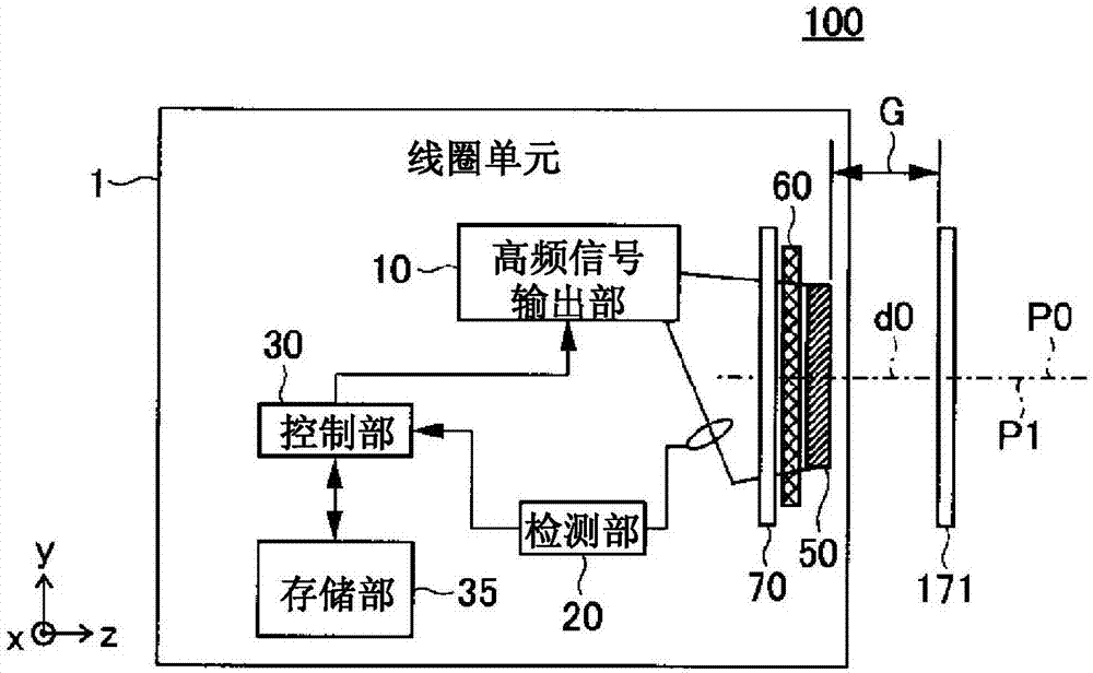
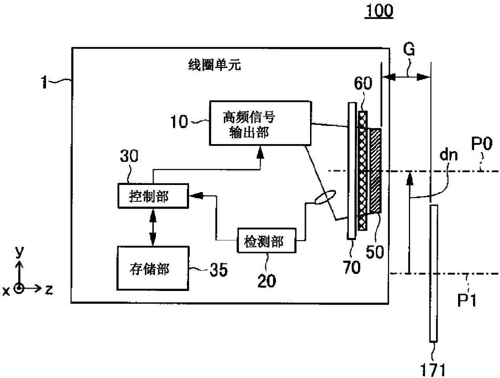
[0037] figure 1 It is a schematic configuration diagram of the contactless power supply device according to the first embodiment of the present invention. refer to figure 1 The non-contact power supply device will be described.

[0038] figure 1 The illustrated wireless power supply device 100 includes a coil unit 1 and a metal plate 171 that perform a power receiving function for wireless power supply. The coil unit 1 is configured to be movable. figure 1 In, the moving direction of the coil unit 1 is set as the first direction (y direction), the direction perpendicular to the first direction is set as the second direction (x direction), and the direction perpendicular to the first direction and the second direction is set as The direction is set to the third direction (z direction).

[0039] The coil unit 1 includes a high-frequency signal output unit 10 , a detection unit 20 , a control unit 30 , a storage unit 35 , a coil 50 , a magnetic body 60 , and a shield plate 7...

no. 2 approach

[0067] Next, an example of an elevator (elevator) provided with the contactless power supply device of the first embodiment will be described as a second embodiment.

[0068] Figure 4 It is a schematic block diagram of the elevator of 2nd Embodiment. Figure 4 The elevator 200 of is provided with the contactless power supply device of the first embodiment. The elevator 200 includes a hoistway 80 formed in a building structure, a car 2 (an example of a mobile body) on which a user rides, a traction machine 3, a counterweight 4, and a suspension coil wound around the traction machine 3. The car 2 and the main hoist 5 of the counterweight 4.

[0069] The hoistway 80 is formed in the building structure, and the machine room 82 is installed on the top thereof. The hoisting machine 3 is disposed in the machine room 82 , and a motor (not shown) rotates forward or reverse to wind the main rope 5 , thereby raising and lowering the car 2 . The car 2 is guided up and down in the y d...

no. 3 approach

[0115] Next, an example in which the position of an elevator is detected using the contactless power supply device of the present invention will be described as a third embodiment. In this embodiment, the position of the coil 50 on the moving path (in the hoistway 80 ) is detected by providing metal plates with different shapes on the moving path (each floor) of the car 2 .

[0116] Figure 9 It is a schematic block diagram of the elevator of 3rd Embodiment.

[0117] The first floor (1F) of the elevator 200 is a power supply floor where the coil unit 101 is installed, and the metal plate 171 is installed. A metal plate 172 is installed on the second floor (2F), a metal plate 173 is installed on the third floor (3F), and a metal plate 177 is installed on the first basement floor (B1). The metal plates 171, 172, 173, and 177 have different shapes, respectively.

[0118] Figure 10 It is a figure which shows the example of the shape of metal plate 172,173,177.

[0119] Seen ...


PUM


Abstract

The invention provides a non-contact power supplying device and an elevator. When supplying electric power to the coil unit installed in mobile bodies, such as a riding basket, electric supply time is secured as for a long time as possible. Before one mode of the present invention arrives at a position (electric supply position) in which the coil (50) on the electricity-receiving side carries out a right opposite to the coil (150) on the power transmission side, it measures the gap G of the coil (50) and the metal plate (171), and computes distance of the coil (50) and the coil (150). And based on distance of the coil (50) and the coil (150), control on the power transmission side (setting change etc.) is preliminarily performed before an electric supply start. So, compared with the conventional non-contact power feeding method which controls after a coil on the electricity-receiving side and a coil on the power transmission side carry out a right opposite, electric supply time is securable for a long time.

Description

technical field [0001] The present invention relates to a non-contact power supply device and an elevator with the function of detecting the distance between the power transmission side coil and the power reception side coil. Background technique [0002] With the rise of super high-rise buildings, the elevators installed in the buildings need to achieve long strokes. A typical elevator uses a power supply line called a tail cord suspended from the car to supply power to the equipment in the car. As the length of the elevator travel increases, the accompanying cable becomes longer. Therefore, the mass of the accompanying cable increases. When the length exceeds a certain length, there is a risk that the elevator will not be able to bear its own weight. Therefore, in an elevator with a super long stroke, although it is desired to realize a structure without a traveling cable, the power supply of the equipment in the car becomes a problem. [0003] As a method for supplying ...

Claims


Application Information

Patent Timeline
IPC IPC(8): H02J50/12H02J50/90
Inventor 山田正明森和久大沼直人松本洋平
Owner HITACHI LTD
Why Eureka
Try Eureka