
Cutting structure for submarine gate of injection mold

A latent gate, injection mold technology, applied in the field of injection mold gate cutting, can solve the problems of affecting the appearance quality of products, time-consuming and laborious, and easy to produce cold grains on the surface of products, so as to save the cost of mold test and avoid modification. , The effect of reducing the number of mold trials

Pending Publication Date: 2017-08-11
JIAXING XINYUAN PRECISION MOLD TECH
View PDF14 Cites 0 Cited by
  • Summary
  • Abstract
  • Description
  • Claims
  • Application Information

AI Technical Summary

Problems solved by technology

[0002] When the injection mold is in use, the gate layout position can seriously affect the quality of the product in the mold. In order to improve the quality of the product in the mold, a latent gate insert is usually designed in the mold. This latent gate insert can Arrange the gate at any position close to the product of the mold. When the product is formed, the product needs to be ejected, and the gate of the general injection mold will also be ejected, and then the gate is manually cut by the worker, while the latent gate structure It may cause defects such as cold material lines on the surface of the product that affect the appearance quality of the product. Usually, this problem occurs. Workers will redesign the gate position or replace the structure of the gate to overcome this problem. This method is time-consuming. In order to solve the above problems, it is very necessary to design a new gate structure

Method used


Image

  • Cutting structure for submarine gate of injection mold
  • Cutting structure for submarine gate of injection mold
  • Cutting structure for submarine gate of injection mold

Examples


Embodiment

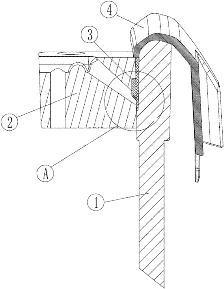
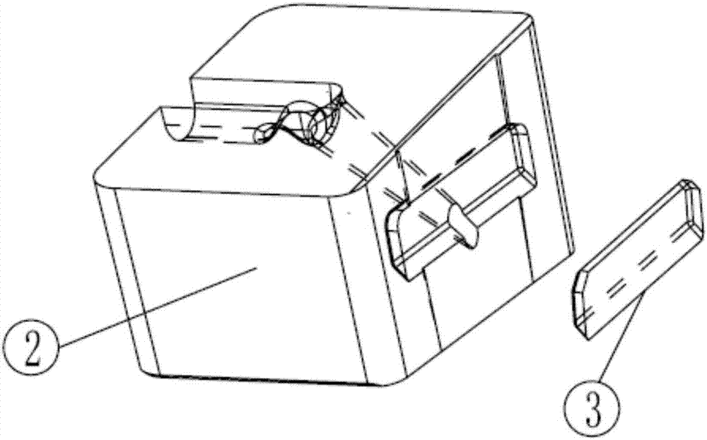
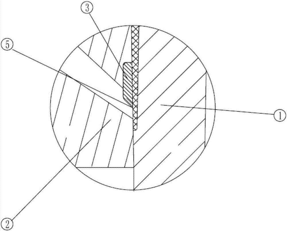
[0024] When the injection mold is producing products, the plastic melt in the molten state is first injected into the cavity of the injection mold through the injection molding machine. Usually, the plastic melt enters the mold cavity from the injection port. In this technology, the plastic melt from The runner hole on the latent gate insert 2 enters the latent gate insert 2, and passes through the gate runner in the latent gate insert 2 from the tool on the side of the latent gate insert 2 The installation groove flows out, and enters the cavity of the injection mold through the runner gap, and then waits for the plastic product 4 to cool and form. After the plastic product 4 is cooled and formed, the mold is opened, and then the straight ejector rod 1 is started to eject the plastic product 4. The cutting edge 5 of the cutter 3 on the latent gate insert 2 cutter mounting groove will cut off the gate and the plastic product 4, so as to prevent the gate and the plastic product ...


PUM

PropertyMeasurementUnit
angleaaaaaaaaaa
hardnessaaaaaaaaaa

Abstract

The invention relates to a cutting structure for a submarine gate of an injection mold. The cutting structure comprises a submarine gate insert, a cutter and a straight ejector rod, wherein the straight ejector rod is arranged on one side of the submarine gate insert; a gate runner is arranged in the submarine gate insert; a cutting mounting groove is formed in the side, close to the straight ejector rod, of each of the gate runner and the submarine gate insert; the cutter is mounted at the upper parts of the cutter mounting grooves in am embedded manner; a runner gap is formed between the upper part of the side, close to the submarine gate insert, of the straight ejector rod and the submarine gate insert; a cutting edge is formed at the lower part of the cutter; and a plastic product communicating with the runner gap is mounted at the upper end of the straight ejector rod. The cutting structure has the characteristics that the structure is simple, the overall structure of the mold does not need to be modified, cold charge marks on the surface of the plastic product in the mold are eliminated, the mold test times of the mold on an injection molding machine is reduced, the mold test cost is lowered, energy saving and environmental protection are achieved, the service life of the mold is prolonged, and mold parts are convenient to replace when damaged.

Description

technical field [0001] The invention relates to the technical field of injection mold gate cutting, in particular to a cutting structure for latent gates of injection molds. Background technique [0002] When the injection mold is in use, the gate layout position can seriously affect the quality of the product in the mold. In order to improve the quality of the product in the mold, a latent gate insert is usually designed in the mold. This latent gate insert can Arrange the gate at any position close to the product of the mold. When the product is formed, the product needs to be ejected, and the gate of the general injection mold will also be ejected, and then the gate is manually cut by the worker, while the latent gate structure It may cause defects such as cold material lines on the surface of the product that affect the appearance quality of the product. Usually, this problem occurs. Workers will redesign the gate position or replace the structure of the gate to overcome...

Claims


Application Information

Patent Timeline
Patent Type & Authority Applications(China)
IPC IPC(8): B29C45/26B29C45/38
CPCB29C45/26B29C45/38
Inventor 刘黄军舒友祥黄顺华
Owner JIAXING XINYUAN PRECISION MOLD TECH
Learn More