Cable winder

A wire winding device and cable technology, applied in the field of electric power, can solve the problems of not being suitable for small-sized cable winding, unfavorable to the health of workers, and the volume of the wire winding device is large, and achieves the effects of simple structure, reduced equipment investment, and reduced cost.

Active Publication Date: 2017-08-11
华远高科电缆有限公司
View PDF6 Cites 7 Cited by
  • Summary
  • Abstract
  • Description
  • Claims
  • Application Information

AI Technical Summary

Problems solved by technology

[0002] In order to facilitate transportation and power operation, after the cable is manufactured, it needs to be wound and wound into a coiled cable coil. At present, the coil winders on the market are large in size, difficult to carry, occupy a large area, and have a narrow scope of application, so they are not suitable for Small-sized cables are used for winding, and a lot of dust will be raised during the winding process, which is not conducive to the health of workers

Method used


Image

  • Cable winder
  • Cable winder
  • Cable winder

Examples


Embodiment Construction

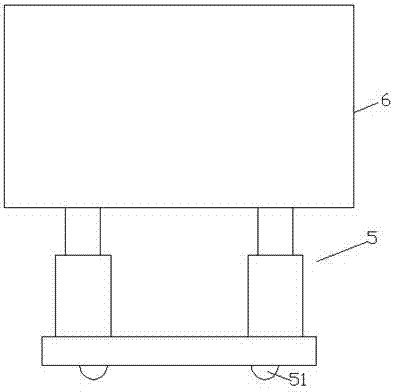
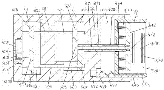
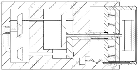
[0021] Such as Figure 1-Figure 5 As shown, a cable winder of the present invention includes a hydraulic lifting device 5 and a winding mechanism 6 arranged on the top of the hydraulic lifting device 5, and a storage tank is provided inside the right side of the winding mechanism 6 63, the storage tank 63 is slidably connected with a closing sleeve 64, the inside of the closing sleeve 64 is provided with a winding cavity 641, and the inside of the winding mechanism 6 on the left side of the storage tank 63 is provided with a transfer cavity 62, A first partition 66 is provided between the transfer cavity 62 and the storage tank 63, and a drive cavity 61 is provided inside the winding mechanism 6 on the left side of the transfer cavity 62, and the drive cavity 61 is connected to the storage tank 63. A second partition 65 is provided between the transfer chambers 62, and the inner bottom of the transfer chamber 62 is provided with a first sliding groove 623, and the first partit...


PUM


Abstract

The invention discloses a cable winder. The cable winder comprises an oil pressure increasing device and a winding mechanism, wherein the winding mechanism is arranged at the top of the oil pressure increasing device; a storage groove is formed inside the right side surface of the winding mechanism; the storage groove is slidably connected with a closed sleeve in a matching manner; a winding chamber is arranged inside the closed sleeve; at the left side of the storage groove, the winding mechanism is internally provided with a conveying chamber; a first separating part is arranged between the conveying chamber and the storage groove; at the left side of the conveying chamber, the winding mechanism is internally provided with a driving chamber; a second separating part is arranged between the driving chamber and the conveying chamber; the inner bottom of the conveying chamber is provided with a first slidable connecting groove; the inside of the first separating part is slidably matched and connected with a connecting rod which is arranged in a manner of extending towards the left and right sides; the right side extending section of the connecting rod extends into the storage groove and extends into the winding chamber by penetrating through the closed sleeve; a push plate is fixedly arranged at the tail of the right side extending section of the connecting rod; a first duct arranged in a manner of extending towards the left direction and right direction is formed inside the connecting rod. The cable winder disclosed by the invention is simple in structure, reasonable in design, capable of reducing space occupation and low in manufacturing cost and maintenance cost.

Description

technical field [0001] The invention relates to the technical field of electric power, and relates to a cable winder. Background technique [0002] In order to facilitate transportation and power operation, after the cable is manufactured, it needs to be wound and wound into a coiled cable coil. At present, the coil winders on the market are large in size, difficult to carry, occupy a large area, and have a narrow scope of application, so they are not suitable for Small-sized cables are used for winding, and a large amount of dust will be raised during the winding process, which is not conducive to the health of workers. Contents of the invention [0003] The technical problem to be solved by the present invention is to provide a cable winder, which can solve the above-mentioned problems in the prior art. [0004] The present invention is achieved through the following technical solutions: A cable winder of the present invention includes an oil pressure lifting device and...

Claims


Application Information

Patent Timeline
Patent Type & Authority Applications(China)
IPC IPC(8): B65H54/40
CPCB65H54/40B65H2701/34
Inventor 张明
Owner 华远高科电缆有限公司
Why Eureka
Try Eureka