rail grinding machine

A grinding machine and rail technology, applied in the direction of rail, laying rail, rail maintenance, etc., can solve the problems of inability to directly adjust the grinding direction, inconvenient for continuous rail grinding, inconvenient transportation and use, etc., and achieve material saving, weight reduction, and convenient operation. Effect

Inactive Publication Date: 2018-11-16
CHONGQING UNIV OF TECH
View PDF6 Cites 0 Cited by
  • Summary
  • Abstract
  • Description
  • Claims
  • Application Information

AI Technical Summary

Problems solved by technology

[0003] But the existing rail grinding machine still has the following defects: 1. Usually, a box body or a plate-shaped steel structure frame is used to ensure the strength of the frame structure, but the weight of the whole machine is relatively large, and transportation and use are inconvenient
2. During the operation, it is necessary to constantly adjust the handle to control the feeding and retracting of the grinding wheel to ensure the effect of profiling grinding, which is inconvenient to operate and low in efficiency
3. Generally, only one side of the rail can be ground, and the grinding direction cannot be directly adjusted. It is inconvenient to realize continuous grinding of multiple sides of the rail.

Method used


Image

  • rail grinding machine
  • rail grinding machine

Examples


specific Embodiment approach

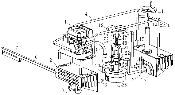
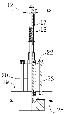
[0027] Specific implementation methods: such as Figure 1-2 As shown, a rail grinding machine includes a body, the body is provided with walking wheels for walking on the rail, the body is also provided with a grinding wheel device and a power machine 1, and the power machine 1 is connected to the grinding wheel device through a transmission mechanism; its characteristics are , the body includes two supporting shells 2 arranged side by side at intervals, and a running wheel 3 is arranged under the two supporting shells 2, and the two supporting shells 2 are fixedly connected as a whole through a connecting steel pipe 4, and the grinding wheel device A grinding wheel for rail grinding is arranged below, the lower surface of the grinding wheel is the grinding surface, and the grinding wheel device is installed between the two supporting shells through a rotation adjustment mechanism, which can adjust the grinding surface of the grinding wheel to rotate along the axis of the machi...


PUM


Abstract

The invention discloses a grinding machine for a steel rail. The grinding machine comprises a machine body, wherein walking wheels which can walk on the steel rail are arranged on the machine body; a grinding wheel device and a power machine are arranged on the machine body; the power machine is connected with the grinding wheel device through a driving mechanism. The grinding machine is characterized in that the machine body comprises two support shells which are arranged in parallel at an interval; the walking wheels are arranged under the two support shells; the two support shells are integrally fixed with each other through a connecting steel pipe; a grinding wheel which is used for grinding the steel rail is arranged under the grinding wheel device; a grinding surface is arranged on the lower surface of the grinding wheel; the grinding wheel device is arranged between the two support shells through a rotating adjusting mechanism; the rotating adjusting mechanism can adjust the grinding surface of the grinding wheel and can rotate along the axis, namely, the walking direction of the machine body; the power machine is arranged on any one of the support shells; an output shaft of the power machine is connected with an input end of the grinding wheel device through a soft shaft. The grinding machine for the steel rail has the advantages of high structure stability, low total weight, convenient operation and flexible adjustment and is capable of realizing the continuous grinding of each side wall of the steel rail.

Description

technical field [0001] The invention relates to the field of railway track maintenance, in particular to a rail grinding machine. Background technique [0002] Rail grinding machine is a kind of mechanical equipment used to grind rails to achieve derusting, maintenance, maintenance and other effects. The traditional rail grinding machine is mainly composed of main components such as a frame, a transmission system, a grinding wheel, and a traveling device. The utility model has the advantages of simple structure and convenient use, and can better realize grinding of steel rails. [0003] But existing rail grinding machine, still there is following defect: 1, usually adopt box body or plate-shaped steel structure frame to guarantee the intensity of frame structure, but cause complete machine weight bigger, transport and use inconvenience. 2. In the process of operation, it is necessary to constantly adjust the handle to control the feeding and retracting of the grinding whee...

Claims


Application Information

Patent Timeline
Patent Type & Authority Patents(China)
IPC IPC(8): E01B31/17
CPCE01B31/17
Inventor 胡青松张晋西李洋陈奕婷肖思伟陈江洪
Owner CHONGQING UNIV OF TECH
Why Eureka
Try Eureka