a sealing valve

A technology for sealing valves and sealing surfaces, which is applied in the direction of lifting valves, valve devices, valve details, etc., and can solve problems such as unsatisfactory sealing, coking of ball valves, secondary cracking, and coking

Active Publication Date: 2019-02-22
朱书红
View PDF6 Cites 0 Cited by
  • Summary
  • Abstract
  • Description
  • Claims
  • Application Information

AI Technical Summary

Problems solved by technology

The best way to remove high-temperature dust is to use high-temperature filter and dust removal equipment. However, after filtering for a period of time, a thick layer of filter cake will form on the surface of the filter element, and the air permeability will be greatly reduced. You must switch to another high-temperature filter and dust removal equipment. When switching high-temperature gas, the valves that need to be closed must be closed tightly, especially the filter element in the high-temperature filter and dust removal equipment needs to be regenerated, otherwise safety accidents will easily occur
However, so-called high-temperature-resistant sealing materials such as silicone rubber, fluororubber, and polytetrafluoroethylene cannot meet the high-temperature environment above 400 ° C. High-temperature-resistant sealing materials such as graphite packing are not flexible, so they can only be used in high-temperature static sealing environments. For example, for coal gas, especially for gas that is prone to secondary cracking and coking at high temperature, tar will be precipitated at low temperature, and tar will be precipitated at high temperature. Secondary cracking and coking occur, and such an environment has stricter requirements on valves
The so-called high-temperature sealed ball valves and high-temperature sealed hemispherical valves sold on the market cannot meet the sealing requirements of this environment. Either the seal is burned out and air leaks, or the ball valve is coked and does not rotate.

Method used


Image

  • a sealing valve
  • a sealing valve
  • a sealing valve

Examples


Embodiment 1

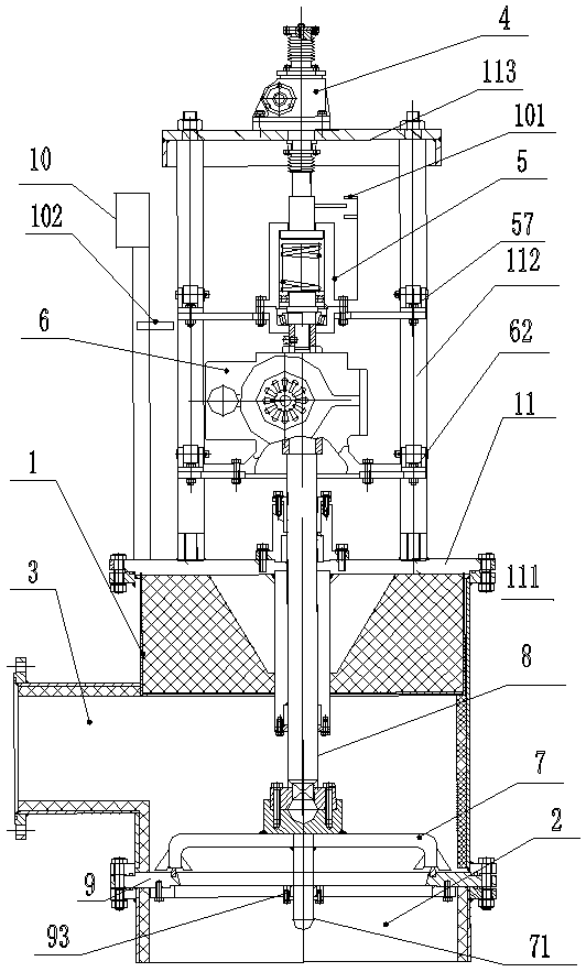
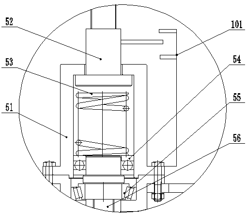
[0033] Embodiment one: as figure 1 , image 3 , Figure 4As shown, a sealing valve includes a valve body 1, an air inlet 2, an air outlet 3, a valve core opening and closing mechanism 4, a load control mechanism 5, a valve core rotating mechanism 6, a valve core 7, and a valve stem 8. The valve body 1 is provided with an air inlet 2 and an air outlet 3, the air inlet 2 is provided with a valve seat 9, the valve seat 9 is connected with the valve core 7, and the valve core 7 is connected with the valve stem 8 , the valve stem 8 passes through the valve body 1 and is connected to the valve core rotating mechanism 6, and the valve core rotating mechanism 6 is connected to the valve core opening and closing mechanism 4 through the load control mechanism 5, and the valve The rotary motion of the core rotating mechanism 6 and the linear motion of the valve core opening and closing mechanism 4 become relatively independent motions through the load control mechanism 5 .

[0034] Th...

Embodiment 2

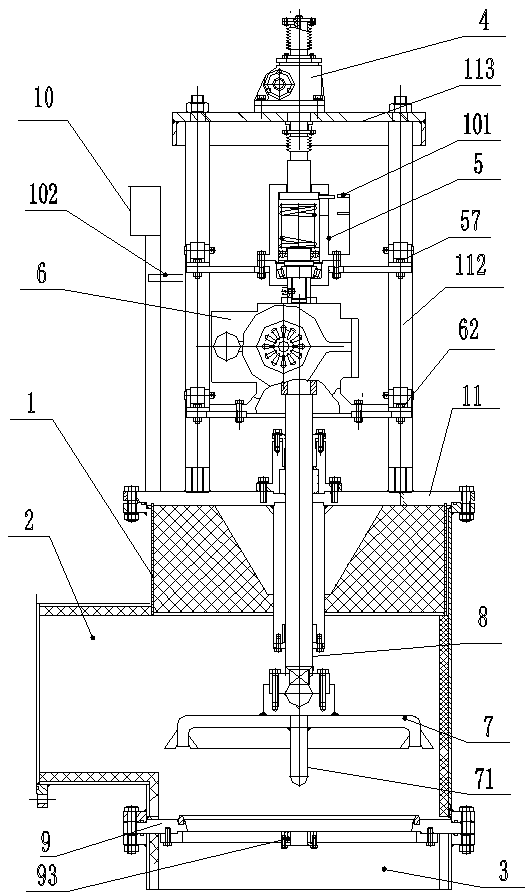
[0047] Embodiment two: if figure 2 , image 3 , Figure 4 As shown, a sealing valve includes a valve body 1, an air inlet 2, an air outlet 3, a valve core opening and closing mechanism 4, a load control mechanism 5, a valve core rotating mechanism 6, a valve core 7, and a valve stem 8. The valve body 1 is provided with an air inlet 2 and an air outlet 3, and the air outlet 3 is provided with a valve seat 9, the valve seat 9 is connected with the valve core 7, and the valve core 7 is connected with the valve stem 8, The valve stem 8 passes through the valve body 1 and is connected to the valve core rotating mechanism 6, the valve core rotating mechanism 6 is connected to the valve core opening and closing mechanism 4 through the load control mechanism 5, and the valve core The rotary motion of the rotating mechanism 6 and the linear motion of the valve core opening and closing mechanism 4 become relatively independent motions through the load control mechanism 5 .

[0048] ...


PUM


Abstract

The invention discloses a seal valve. The seal valve comprises a valve body, an air inlet, an air outlet, a valve element opening and closing mechanism, a load control mechanism, a valve element rotating mechanism, a valve element and a valve rod, wherein the air inlet and the air outlet are formed in the valve body; a valve seat is arranged at the air inlet or the air outlet and is in contact with the valve element; the valve element is connected with the valve rod; the valve rod penetrates the valve body and is connected with the valve element rotating mechanism; the valve element rotating mechanism is connected with the valve element opening and closing mechanism through the load control mechanism; and rotary motion of the valve element rotating mechanism and linear motion of the valve element opening and closing mechanism are changed into relatively independent motions through the load control mechanism. According to the seal valve, the opening and closing force and the rotating, driving and grinding resistance are controlled by the load control mechanism, so that the seal valve has reliable leakproofness.

Description

technical field [0001] The invention relates to the technical field of valves, in particular to a gas sealing valve in a high-temperature environment containing dust and tar. Background technique [0002] The dry distillation and pyrolysis process of coal produces a large amount of gas, which contains dust and tar, especially in the pyrolysis process of pulverized coal in the rotary kiln, the gas contains a large amount of coal tar and coal powder, and coal tar is an important product oil and For chemical raw materials, if a large amount of coal powder enters coal tar, it will seriously affect the deep processing of coal tar. This requires that coal tar must be separated from dust in the gaseous state. Otherwise, once coal tar and coal powder are mixed together, it will be difficult to separate. The separation of tar and dust must be in the gaseous state, so the gas must be dedusted at high temperature, and the spray cooling method cannot be used after the gas leaves the rot...

Claims


Application Information

Patent Timeline
Patent Type & Authority Patents(China)
IPC IPC(8): F16K1/36F16K1/32F16K31/12F16K31/04F16K31/50F16K49/00F16K27/02
CPCF16K1/32F16K1/36F16K27/02F16K31/04F16K31/12F16K31/50F16K49/002
Inventor 朱书红
Owner 朱书红
Why Eureka
Try Eureka