Experimental device for biomechanical property testing of patellar joint

A biomechanical and experimental device technology, applied in the direction of using a stable bending force to test the strength of a material, and using a stable tension/pressure to test the strength of the material, etc., can solve problems such as limiting the load level, and achieve a small occupied space and a solid structure. Effect

Active Publication Date: 2017-08-11
SHANGHAI UNIV
View PDF7 Cites 7 Cited by
  • Summary
  • Abstract
  • Description
  • Claims
  • Application Information

AI Technical Summary

Problems solved by technology

This limits the number of variables that can be evaluated for a single specimen or the load level at which the test is executable

Method used


Image

  • Experimental device for biomechanical property testing of patellar joint
  • Experimental device for biomechanical property testing of patellar joint
  • Experimental device for biomechanical property testing of patellar joint

Examples


Embodiment Construction

[0023] Below in conjunction with accompanying drawing and preferred embodiment the present invention is described in further detail:

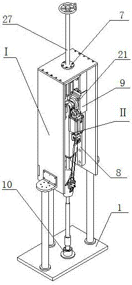
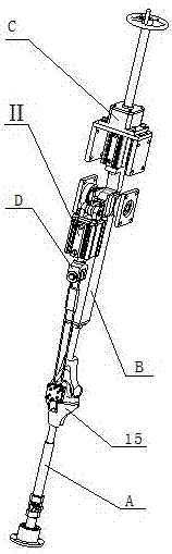
[0024] Such as figure 1 As shown, an experimental device for testing the biomechanical properties of the patella joint, including a frame assembly I and a joint assembly II; the frame assembly I is a frame structure, and the joint assembly II is installed on the frame assembly I Above; the ankle 10 at the bottom of the joint assembly II and the frame bottom plate 1 are connected by bolts, and the guide rail slider 21 in the joint assembly II and the linear guide rail slider 9 in the frame assembly I are fixed by bolts; The adjusting screw 27 forms a thread pair with the screw sleeve 7 in the frame assembly I, and the position of the top part C in the joint assembly II is adjusted by rotating the adjusting screw 27, thereby realizing the flexion action of the knee joint model 15.

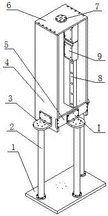
[0025] Such as figure 2 As shown, the frame assembly 1 includ...


PUM


Abstract

The invention relates to an experimental device for biomechanical property testing of a patellar joint. The experimental device comprises a framework assembly and a joint assembly, wherein the framework assembly adopts a framework structure, and the joint assembly is mounted on the framework assembly; an ankle part at the bottom of the joint assembly is connected with a framework bottom plate through a bolt, a guide rail sliding block in the joint assembly is fixedly connected with a linear guide rail sliding block in the framework assembly through a bolt; an adjustment screw rod in the joint assembly and a screw rod sleeve in the framework assembly form a threaded pair, and bending of a knee joint model is realized by rotating the adjustment screw rod to adjust the position of the top of joint assembly. The experimental device can be used for simulating biomechanics of the patellar joint at different bending angles of the knee joint. The bending angle of the knee joint can be adjusted as required, and the experimental device is reliable in fixation and can guarantee correctness of an experiment.

Description

technical field [0001] The invention relates to an experimental device for testing biomechanical properties, in particular to an experimental device for testing biomechanical properties of patella joints. Background technique [0002] Increasing life expectancy in developed regions, coupled with rising obesity rates, is driving unprecedented growth in total knee replacement surgery. However, the complications of knee replacement surgery also plague a considerable number of patients with knee joint disease. Some patients reported difficulty in stretching the lower limbs or knee prodromal pain after surgery, and the direct cause was poor biomechanics of the patellar joint. [0003] The knee joint is the largest and most complex joint in the human body. At the same time, due to the diversity of living individuals and the limitations of ethics and morality on in vivo research, researchers cannot directly test the different statically stable structures around the knee joint. Ass...

Claims


Application Information

Patent Timeline
Patent Type & Authority Applications(China)
IPC IPC(8): G01N3/10G01N3/20
Inventor 唐明瑶雷静桃张恒
Owner SHANGHAI UNIV
Why Eureka
Try Eureka