Vehicle path planning method based on storage unmanned vehicle
A vehicle path and local path planning technology, applied in vehicle position/route/height control, motor vehicles, two-dimensional position/channel control, etc., can solve the problem of inability to solve optimization and obstacle avoidance at the same time, difficult positioning, flexible Poor performance and other problems, achieve the effect of short running distance, optimize topology nodes, and improve work efficiency
- Summary
- Abstract
- Description
- Claims
- Application Information
AI Technical Summary
Problems solved by technology
Method used
Image

Examples
Embodiment
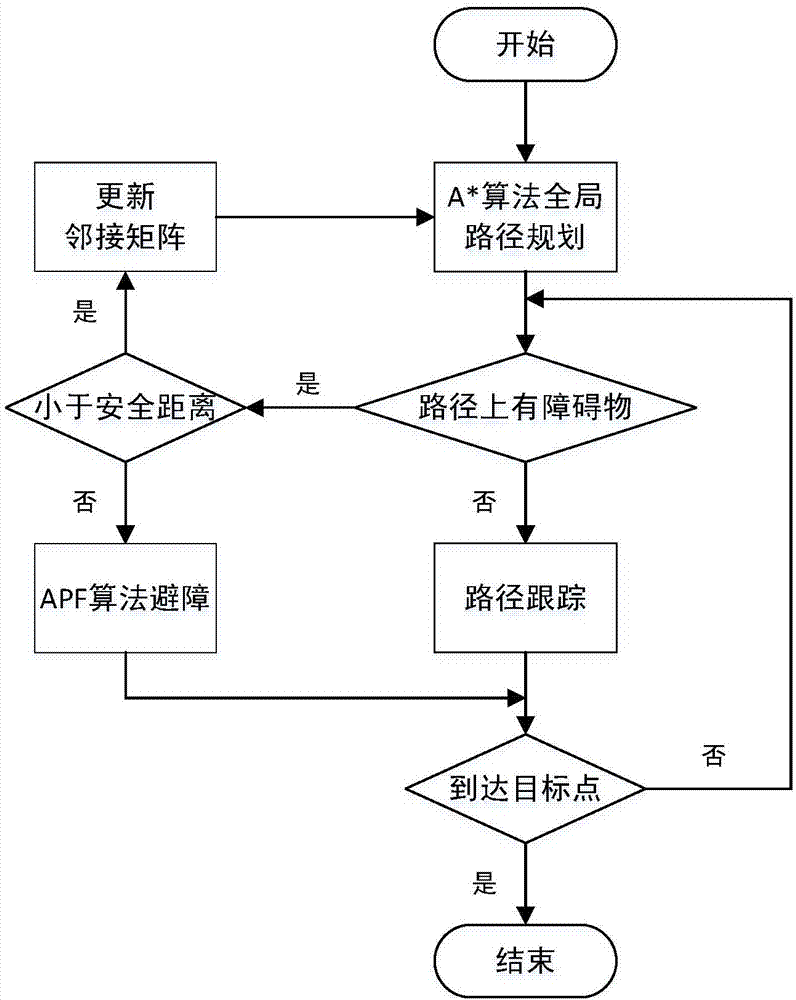
[0058] to combine figure 1 , the present invention is based on a vehicle path planning method for warehouse unmanned vehicles, and the specific implementation steps are as follows:
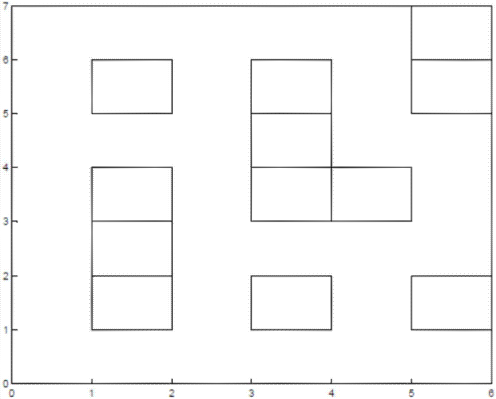
[0059] Step 1. Make a topological map of the storage environment, such as figure 2 Shown is a schematic map of the storage environment. The rectangles in the figure represent the shelves. Collect the relative positions of the feasible path of the unmanned vehicle in the storage environment and the shelf. According to the collected information, set the nodes that the unmanned vehicle can reach, and then create an The adjacency matrix of the topological map;
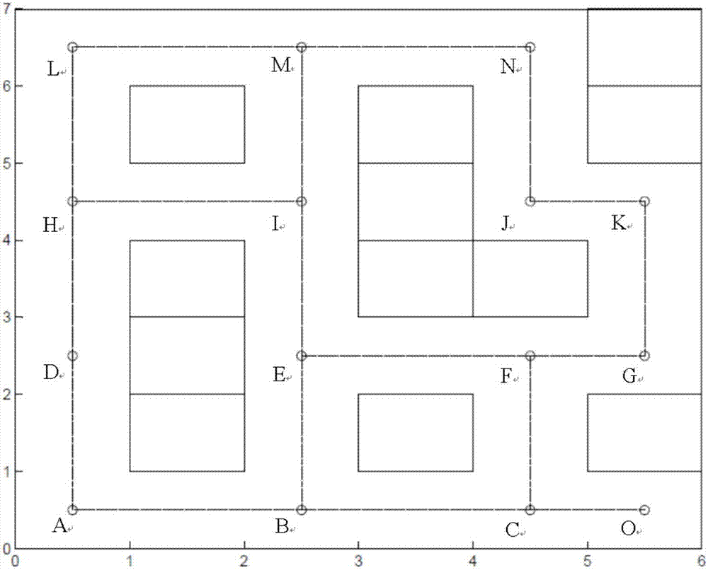
[0060] Step 1-1, such as image 3 As shown in Fig. 1, the environment map information is collected, and the inflection point of each intersection and the point where the unmanned vehicle needs to stop in the environment map is used as a topological node, and the road connected to the topological node is used as a topological edge, so the en...
PUM
 Abstract
Description
Claims
Application Information
 - R&D
- Intellectual Property
- Life Sciences
- Materials
- Tech Scout
- Unparalleled Data Quality
- Higher Quality Content
- 60% Fewer Hallucinations
Browse by: Latest US Patents, China's latest patents, Technical Efficacy Thesaurus, Application Domain, Technology Topic, Popular Technical Reports.
© 2025 PatSnap. All rights reserved.Legal|Privacy policy|Modern Slavery Act Transparency Statement|Sitemap|About US| Contact US: help@patsnap.com