Method and device for determining finite element point load distribution in aircraft wing

A finite element and point load technology, used in special data processing applications, instruments, electrical and digital data processing, etc., can solve the problems of poor load distribution accuracy, harsh three-point arrangement, and inability to guarantee the rationality of distribution. High practicability, high practicability and high accuracy

Active Publication Date: 2017-08-11
SHANGHAI GONGFANG SOFTWARE CO LTD
View PDF4 Cites 12 Cited by
  • Summary
  • Abstract
  • Description
  • Claims
  • Application Information

AI Technical Summary

Problems solved by technology

[0005] The conditions that the three-point row scheme needs to meet are too harsh. For some aerodynamic points, the nearest three finite element points are found, but they do not fall into the triangular area formed by them. The allocation cannot be handled, and

Method used


Image

  • Method and device for determining finite element point load distribution in aircraft wing
  • Method and device for determining finite element point load distribution in aircraft wing
  • Method and device for determining finite element point load distribution in aircraft wing

Examples


Embodiment 1

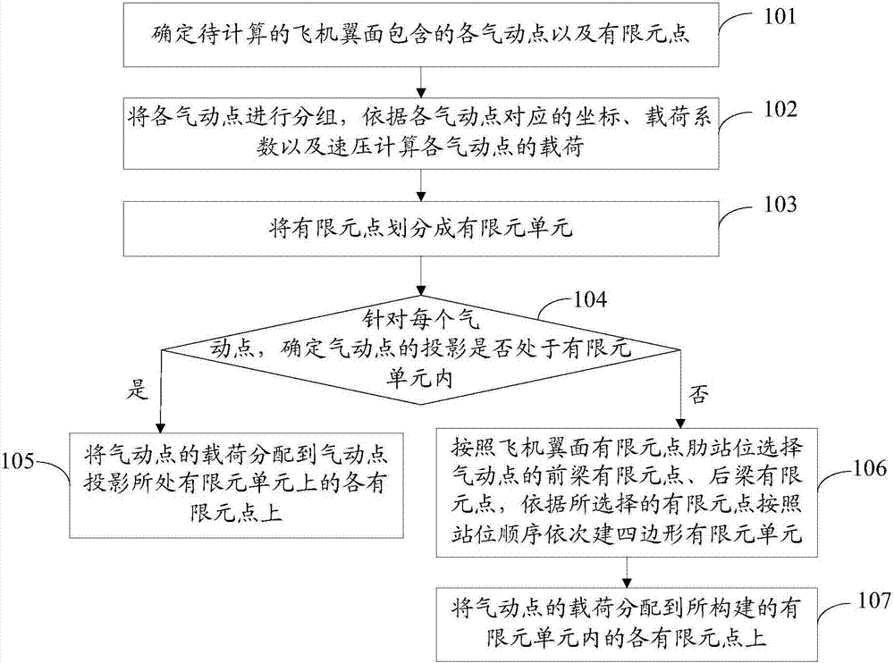
[0031] refer to figure 2 , shows a flow chart of steps of a method for determining the distribution of finite element point loads on an aircraft wing surface according to Embodiment 1 of the present invention.

[0032] The method for determining the finite element point load distribution in the aircraft wing surface of the embodiment of the present invention comprises the following steps:

[0033] Step 101: Determine the aerodynamic points and finite element points contained in the aircraft wing surface to be calculated.

[0034] In the actual application process, it is necessary to calculate the load on and under the left wing of the aircraft, and the load on and under the right wing. In the embodiment of the present invention, the calculation of a single plane on a single wing of an aircraft is taken as an example for illustration. In the specific implementation process, the method provided in the embodiment of the present invention can be repeatedly used to determine the...

Embodiment 2

[0056] refer to Figure 4 , shows a flow chart of steps of a method for determining the distribution of finite element point loads on an aircraft wing surface according to Embodiment 2 of the present invention.

[0057] The method for determining the finite element point load distribution in the aircraft wing surface of the embodiment of the present invention comprises the following steps:

[0058] Step 201: Determine the aerodynamic points and finite element points included in the aircraft wing surface to be calculated.

[0059] The method for determining the finite element point load distribution in the aircraft wing surface in the embodiment of the present invention is executed by a computer program preset in the computer. In the actual application process, it is necessary to calculate the load on and under the left wing of the aircraft, and the load on and under the right wing. In the embodiment of the present invention, the calculation of a single plane on a single wing...

Embodiment 3

[0122] refer to Figure 8 , shows a structural block diagram of a device for determining the distribution of finite element point loads in an aircraft wing surface according to Embodiment 3 of the present invention.

[0123] The device for determining the finite element point load distribution in the aircraft wing surface of the embodiment of the present invention includes: a first determination module 301, which is used to determine each aerodynamic point and finite element point included in the aircraft wing surface to be calculated; a load calculation module 302, which is used to Each aerodynamic point is grouped, and the load of each aerodynamic point is calculated according to the coordinates, load coefficients, and velocity pressures corresponding to each aerodynamic point; the unit division module 303 is used to divide the finite element points into finite element units, wherein the finite element units are triangular or quadrilateral, each finite element unit contains ...


PUM


Abstract

The invention provides a method and a device for determining finite element point load distribution in an aircraft wing. The method comprises the steps that all pneumatic points and finite element points contained in the aircraft wing to be calculated are determined; all the pneumatic points are grouped, and loads of all the pneumatic points are calculated according to coordinates, load coefficients and velocity pressure corresponding to all the pneumatic points; the finite element points are divided into finite element units; whether a projection of each pneumatic point is in one finite element unit is determined; if yes, the loads of the pneumatic points are distributed to all the finite element points on the finite element units where the projections of the pneumatic points are located; if not, front-beam finite element points and back-beam finite element points of the pneumatic points are selected according to rib stances of the finite element points in the aircraft wing, and quadrilateral finite element units are sequentially constructed according to the order of the stances and the selected finite element points; and the loads of the pneumatic points are distributed to all the finite element points in the constructed finite element units. Through the load distribution method, the accuracy of a calculation result is high.

Description

technical field [0001] The invention relates to the technical field of calculation of finite element point loads on aircraft wings, in particular to a method and a device for determining the distribution of finite element point loads on an aircraft wing surface. Background technique [0002] The loads that the aircraft wing structure needs to bear include aerodynamic loads, inertial loads and concentrated force loads. When performing finite element calculations, it is necessary to map aerodynamic loads, inertial loads, and concentrated force loads to finite element points. The mapping results must satisfy that the total load and total moment are equal, and the position of the center of pressure remains unchanged. Since the mapping method is a numerical method, there is a problem of distribution accuracy, and the distributed load needs to be trimmed and shared. Different solution methods will have different results. Therefore, the authenticity of the load distribution on the ...

Claims


Application Information

Patent Timeline
IPC IPC(8): G06F17/50
CPCG06F30/15G06F30/23
Inventor 牟全臣姚立民雒森
Owner SHANGHAI GONGFANG SOFTWARE CO LTD
Why Eureka
Try Eureka