
Multifunctional protective pressure plate

A multi-functional technology for protecting the pressure plate, applied in the direction of contact parts, electrical components, coupling devices, etc., can solve the problems of screw hole blockage, lower power transmission efficiency, etc., and achieve the purpose of preventing the compression spring from falling off, preventing free slippage, and good electrical contact Effect

Active Publication Date: 2017-08-11
NANYANG POWER SUPPLY COMPANY OF STATE GRID HENAN ELECTRIC POWER
View PDF5 Cites 2 Cited by
  • Summary
  • Abstract
  • Description
  • Claims
  • Application Information

AI Technical Summary

Problems solved by technology

[0005] The disadvantages of the above two structures are: since the protective pressure plate is installed on the power cabinet, the power cabinet is a long-term working and charged device, which is easy to cause the problem of blockage of the screw holes for accommodating the studs. Since the above two structures do not A spare protective pressure plate is set, so it is necessary to clean the screw holes or replace a new protective pressure plate, which reduces the power transmission efficiency virtually.

Method used


Image

  • Multifunctional protective pressure plate
  • Multifunctional protective pressure plate
  • Multifunctional protective pressure plate

Examples


Embodiment 1

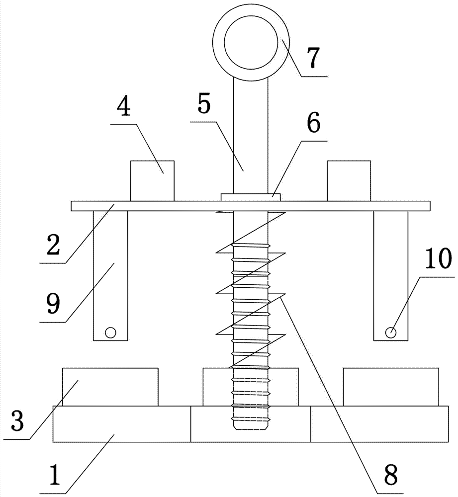
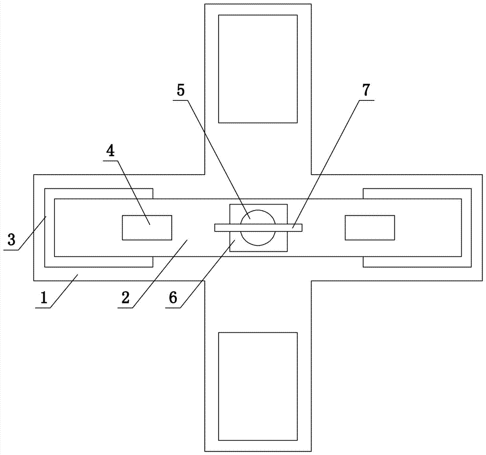
[0033] Such as Figure 1 to Figure 3 As shown, the present invention discloses a multifunctional protective pressure plate, which includes an insulating plate 1 and a conductive plate 2. The insulating plate 1 is in the shape of a cross or a rice. This embodiment adopts a cross-shaped structure. The end faces are all fixedly connected to the insulating pad 3, the center of the insulating pad 3 is provided with a first through hole (not shown in the figure), the center of the insulating plate 1 is provided with a threaded through hole (not shown in the figure), and the threaded through hole is parallel to the first through hole Setting, the upper end surface of the conductive plate 2 is provided with an insulating dial 4, and the center of the conductive plate 2 is provided with a second through hole (not shown in the figure), and a screw 5 is arranged in the second through hole, and the screw 5 is fixedly connected to the baffle 6, and the screw 5 The upper end is provided wit...

Embodiment 2

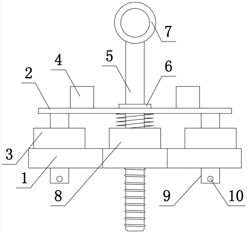
[0036] Such as Figure 4 to Figure 6 As shown, the present invention discloses a multifunctional protective pressure plate, comprising an insulating plate 1 and a conductive plate 2, the insulating plate 1 is cross-shaped, and the upper end surfaces of the four ends of the insulating plate 1 are fixedly connected to the insulating pads 3, and the insulating pads A first through hole (not shown) is provided in the center of the block 3, a threaded through hole (not shown in the figure) is provided on the insulating plate 1, the threaded through hole is arranged in parallel with the first through hole, and an insulating switch 4 is provided on the upper end of the conductive plate 2 , there are two insulating dials 4, a second through hole (not shown in the figure) is opened in the center of the conductive plate 2, a screw 5 is arranged in the second through hole, the screw 5 is fixedly connected to the baffle 6, and the upper end of the screw 5 is provided with a pull Ring 7, t...

Embodiment 3

[0039] The invention discloses a multifunctional protective pressure plate, which comprises an insulating plate 1 and a conductive plate 2. The insulating plate 1 is in the shape of a cross. A first through hole (not shown) is set in the center, and a threaded through hole (not shown) is set in the center of the insulating plate 1. The threaded through hole is arranged in parallel with the first through hole, and the upper end of the conductive plate 2 is provided with an insulating switch 4 to insulate The dial 4 is a circular plate structure and is arranged obliquely. The center of the conductive plate 2 is provided with a second through hole (not shown in the figure), and a screw 5 is arranged in the second through hole. The screw 5 is fixedly connected to the baffle 6, and the screw The upper end of the 5 is provided with a lifting ring 7, and the lower end of the screw rod 5 is threaded through the second through hole to cooperate with the threaded through hole. A compress...


PUM


Abstract

The invention belongs to the technical field of electric power protection equipment and in particular provides a multifunctional protective pressure plate comprising an insulating plate and a conductive plate. The insulating plate is in the shape of a cross or a Chinese character 'Mi', and an insulating pad is arranged on each of a plurality of ends of the insulating plate. A first through hole is arranged at the center of each insulating pad, a thread through hole is arranged in the insulating plate, and the thread through hole is arranged in parallel with the first through hole. An insulating toggle block is arranged on the upper end surface of the conductive plate, and a second through hole is arranged at the center of the conductive plate. A screw is arranged in the second through hole, and a baffle plate is fixedly connected with the screw. The lower end of the screw passes through the second through hole and is threadedly fitted with the thread through hole. A compression spring is arranged between the insulating plate and the conductive plate and sleeves the screw. The conductive plate is between the baffle plate and the compression spring. Conductive columns are arranged on two ends of the conductive plate, and the lengths of the conductive columns are smaller than that of the screw. When one of the first through holes is blocked or dirty, the conductive column at the lower end of the conductive plate is adjusted to cooperate with the different first through holes to ensure the power transmission time.

Description

technical field [0001] The invention belongs to the technical field of electric protection equipment, in particular to a multifunctional protective pressure plate. Background technique [0002] Relay protection and safety automatic devices are the most important secondary equipment in the power system. The protection pressure plate is the bridge for relay protection and safety automatic devices to realize their functions. It is related to whether the protection function and the action outlet can work normally. Depending on the position of the secondary circuit of the inlet protection device, it can be divided into two categories: the protection function pressure plate and the outlet pressure plate. When the system operation mode changes, the protection pressure plate will be switched on and off accordingly. Once the protection pressure plate is mis-operated , misstop, may affect the realization of relay protection and safety automatic device functions, and even cause large-s...

Claims


Application Information

Patent Timeline
IPC IPC(8): H01R13/10H01R13/631H01R13/639H01R13/502
CPCH01R13/10H01R13/502H01R13/631H01R13/639
Inventor 曹艺
Owner NANYANG POWER SUPPLY COMPANY OF STATE GRID HENAN ELECTRIC POWER
Learn More