Root tuber harvester

A harvester and tuber technology, applied in excavating harvesters, harvesters, excavators, etc., can solve the problems of easy congestion, harvesting, and large working resistance of excavating shovels, and achieve the effect of improving work efficiency

Active Publication Date: 2017-08-15
QINGDAO AGRI UNIV
View PDF5 Cites 3 Cited by
  • Summary
  • Abstract
  • Description
  • Claims
  • Application Information

AI Technical Summary

Problems solved by technology

The planting areas of massive rhizome crops in my country are widely distributed and the geographical environment is complex. Although large-scale planting has appeared in many places, the vast rural areas are still dominated by decentralized small-scale production methods; the planting mode is complex, including both ridge farming and flat farming. Moreover, there are various cultivars, and the distance between rows and plants is not uniform, which greatly restricts the development of harvesting machinery for massive rhizomes.
[0003] The existing massive crop harvesters have the following problems: (1) the digging shovel of the existing harvester has a large working resistance, is easy to be congested, and is easy to collapse the shovel, and cannot adapt to the harvesting of roots of different sizes; (2) the massive crops are transported to After the collection box is filled with massive crops, the machine must be shut down, and the full collection box must be removed manually and replaced with an empty collection box before the harvest can continue. The continuous shutdown and restart greatly reduces the harvesting time. machine harvesting efficiency

Method used


Image

  • Root tuber harvester
  • Root tuber harvester
  • Root tuber harvester

Examples


Embodiment Construction

[0025] The present invention will be further described below in conjunction with the accompanying drawings and embodiments.

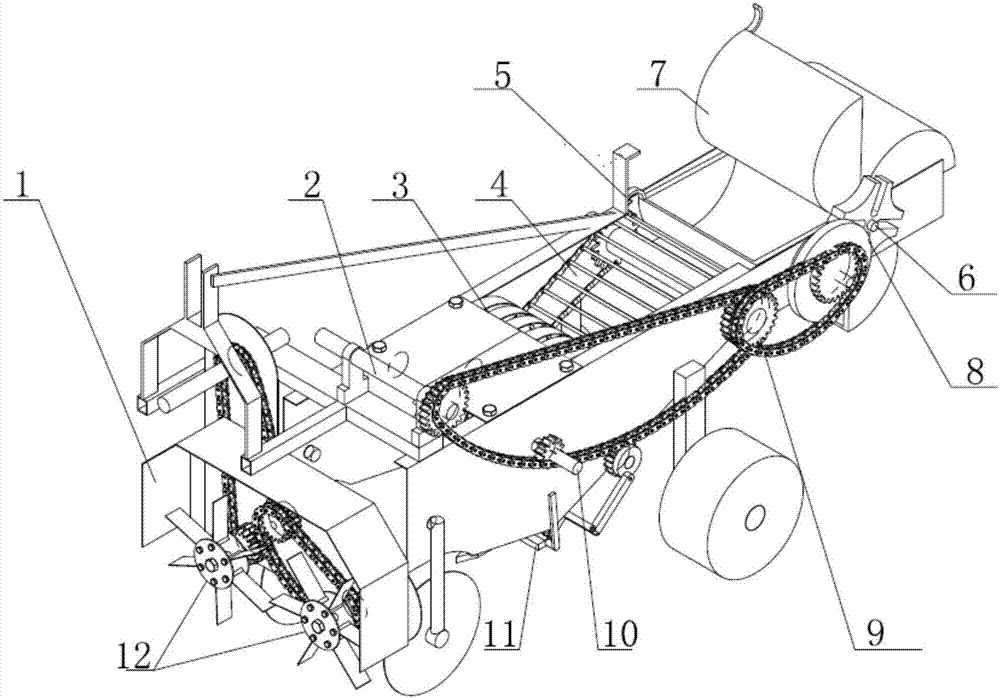
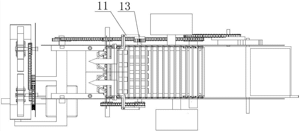
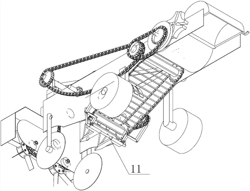
[0026] like Figure 1 to Figure 3 As shown, the root harvester of the present invention includes a frame 1, an excavating device, a conveying device and a stacking device, the excavating device, the conveying device and the stacking device are all arranged on the frame 1, and the excavating device is arranged The conveying device is arranged in the middle of the frame 1, and the stacking device is arranged in the tail of the frame 1.

[0027] Excavation device comprises two pointed shovels 14, pointed shovel spacing adjusting device 11 and earth moving wheel 12, wherein moving earth wheel 12 is arranged on the front end of frame 1, and pointed shovel 14 is connected with pointed shovel spacing adjusting device 11, and pointed shovel 14 and Tip shovel distance adjusting device 11 is positioned at the rear of earthmoving wheel 12. In the present embodim...


PUM


Abstract

The invention relates to crop harvesting equipment and in particular relates to a root tuber harvester comprising a rack, a digging device, a conveying device and a stacking device. The digging device, the conveying device and the stacking device are all arranged on the rack; the conveying device is arranged between the digging device and the stacking device; the digging device is formed by two sharp shovels and a sharp shovel distance adjusting device; the sharp shovels are connected with the sharp shovel distance adjusting device; the sharp shovel distance adjusting device has slide sleeves, fixing racks, L-shaped connection rods, connection rods and rotary discs (II); the sharp shovels are respectively fixed to the slide sleeves; two ends of the fixing rack are fixedly connected with the rack; one ends of the slide sleeves are in a slideable connection with the fixing rack; the sharp shovels are fixed on the other ends of the slide sleeves; the external sides, which faces the rack, of the slide sleeves are connected with the connection rods via the L-shaped connection rods; the other ends of the connection rods are eccentrically connected with the rotary discs (II); right-angle corners of the L-shaped connection rods are hinged with the rack; the rotary discs (II) are fixed on rotary discs (I); and the rotary discs (I) are mounted on the rack. Small soil-penetrating resistance is provided; a collection tank can be automatically exchanged without shutdown when the collection tank is filled, so harvesting efficiency of the harvester can be greatly improved.

Description

technical field [0001] The invention relates to crop harvesting equipment, in particular to a tuber harvester. Background technique [0002] With the development of agricultural mechanization, the research and application of harvesting machinery for massive rhizomes in my country is also increasing. The planting areas of massive rhizome crops in my country are widely distributed and the geographical environment is complex. Although large-scale planting has appeared in many places, the vast rural areas are still dominated by decentralized small-scale production methods; the planting mode is complex, including both ridge farming and flat farming. And the cultivars are diverse, and the row and plant spacing are not uniform, which greatly restricts the development of massive rhizome harvesting machinery. [0003] The existing massive crop harvesters have the following problems: (1) the digging shovel of the existing harvester has a large working resistance, is easy to be congest...

Claims


Application Information

Patent Timeline
Patent Type & Authority Applications(China)
IPC IPC(8): A01D13/00A01D33/10A01D33/08
CPCA01D13/00A01D33/08A01D33/10
Inventor 王方艳
Owner QINGDAO AGRI UNIV
Why Eureka
Try Eureka