Detachable flood and dry dual-purpose rotary embedded knife roller

A dual-use, detachable technology, applied in applications, agricultural machinery and implements, agriculture, etc., can solve the problems of complicated arrangement of rotary tillers, straws that cannot be buried in the ploughing layer, and horizontal helical knives that cannot be disassembled. , to reduce the power consumption of the paddy field, improve the working efficiency, and reduce the vibration.

Inactive Publication Date: 2019-05-07
HUAZHONG AGRI UNIV
View PDF9 Cites 0 Cited by
  • Summary
  • Abstract
  • Description
  • Claims
  • Application Information

AI Technical Summary

Problems solved by technology

The traditional rotary tiller roller has a simple structure and strong versatility, but the serious grass entanglement of the cutter roller causes unnecessary power consumption, and most of the straw cannot be buried in the plow layer, which affects the subsequent sowing and insertion work
The grass-burying knife roller has a good effect of throwing soil and turning the soil and covering it, but the resistance of the horizontal knife to the soil is large, so that the cutting edge wears seriously, the plowing depth is not enough, the power consumption increases sharply, and the efficiency is low
[0003] Invention patent 201410436141.8 "Combined straw returning rotary tiller roller" combines the traditional rotary tiller roller and grass-burying cutter roller in a reasonable combination, and one cutter roller realizes the functions of plowing and grass-burying, but the cutter roller The versatility is not strong, the spiral horizontal knife cannot be disassembled, the arrangement of the rotary tiller is complicated, and the force is uneven
For soils with high firmness (>1260kpa), the rare problem of horizontal knife entry into the soil is still unsolved

Method used


Image

  • Detachable flood and dry dual-purpose rotary embedded knife roller
  • Detachable flood and dry dual-purpose rotary embedded knife roller
  • Detachable flood and dry dual-purpose rotary embedded knife roller

Examples


Embodiment Construction

[0033] Below in conjunction with accompanying drawing, the present invention will be further explained:

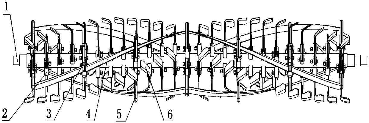
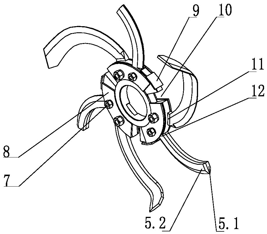
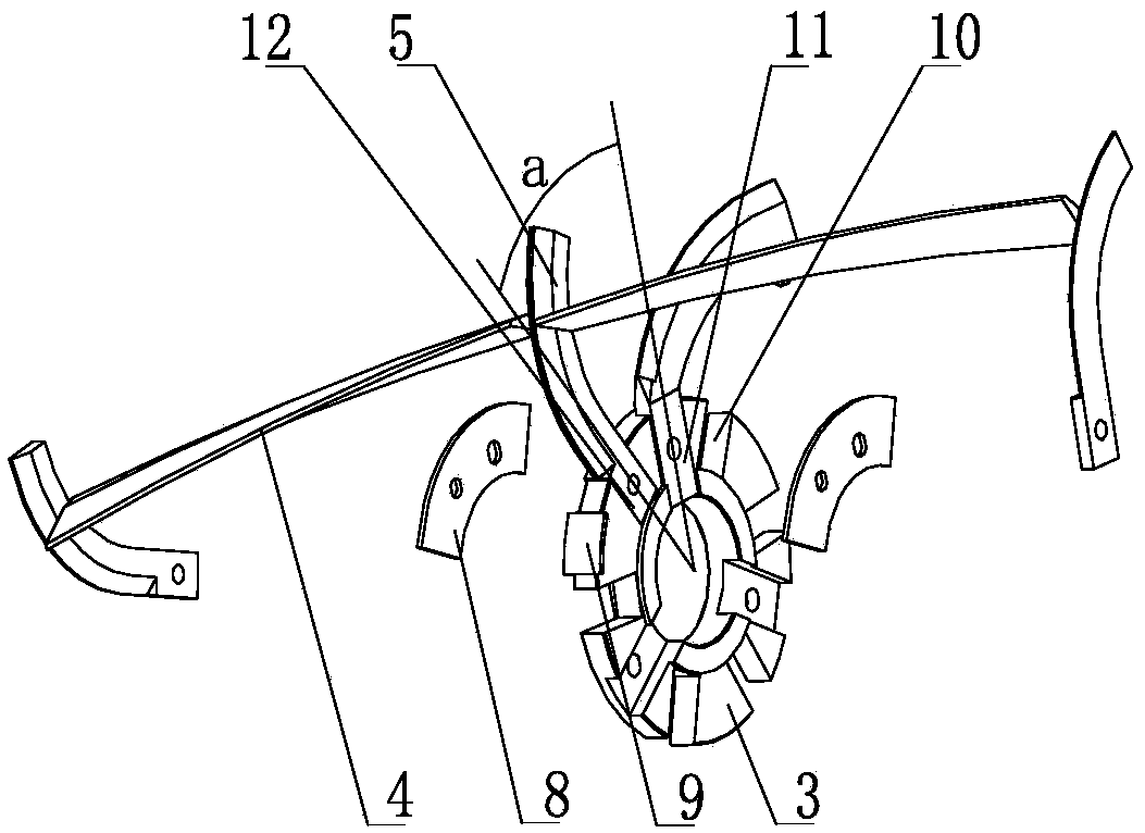
[0034] see figure 1 , figure 2 and image 3 , the cutter roll of the present invention comprises a cutter shaft 1 and a cutter, with the center line of the cutter shaft 1 being the center line of symmetry, the cutters on both sides of the cutter shaft 1 are symmetrically arranged, and the rotary tiller blades 6 on both sides of the cutter shaft 1 are rotated in opposite directions, That is, the rotary tiller 6 in the right-handed direction is installed on the left side of the knife shaft, and the rotary tiller 6 in the left-handed direction is installed on the right side of the knife shaft. The cutter includes a spiral horizontal knife 4, a machete set 5 and a rotary tiller 6, and the machete set 5 is composed of two closely fitted machetes 5.1, 5.2. A plurality of cutter heads 3 are housed on the described cutter shaft 1, and a plurality of cutter holders 2 (9 cutter ...


PUM


Abstract

The invention relates a dismountable amphibious rototillingknife roller which resolves the problems of poor universality, high energy consuming, disable detachingand uneven stress of the knife. The rototillingknife comprises knife tools and a knife shaft. The knife tools comprise rotary blades, lateralscrew blades and curved blades groups. The knife shaft is provided with a plurality of knife disks and the knife shaft between the two adjacentknife disksis provided with a plurality of knife bases that the lateralscrew blades are installed inside,a plurality of the curved blades groups and rotary blades are alternately installed around the edge of the knife disk, and the lateralscrew blades are welded between the adjacent curved blades. On the two sides of the knife shaft, the knife tools are symmetrically arranged, rotating directions of the rotary blades are opposite and in the same rotary interval, the rotary blades and lateralscrew blades are arranged in reverse directions. The knife roller has the advantages of reasonable and compact structure, uniform stress, energy consumingconservation, high working efficiency, and goodreliability, dismounting easily, flexibility and convenience, good universality.

Description

technical field [0001] The invention relates to a cutter roll in agricultural equipment, in particular to a detachable rotary buried cutter roll for both water and dry use. Background technique [0002] Straw returning to the field can not only solve the problem of straw burning indiscriminately, but also is the most direct and economical method to reduce the amount of chemical fertilizers, improve soil quality, and increase soil fertility. The traditional rotary tiller roller has a simple structure and strong versatility, but the serious grass wrapping of the cutter roller causes unnecessary power consumption, and most of the straw cannot be buried into the plow layer, which affects the subsequent sowing and insertion work. The grass-burying knife roller has a good effect of throwing soil and turning the soil and covering it, but the resistance of the horizontal knife to the soil is large, so that the cutting edge wears seriously, the plowing depth is not enough, the power ...

Claims


Application Information

Patent Timeline
Patent Type & Authority Patents(China)
IPC IPC(8): A01B33/10A01B33/12A01B33/14A01D82/00
CPCA01B33/103A01B33/12A01B33/142A01D82/00
Inventor 夏俊芳祝英豪张居敏周勇周华胡梦杰
Owner HUAZHONG AGRI UNIV
Why Eureka
Try Eureka