Greenhouse system and greenhouse plantation method

A technology of greenhouse and shed film, which is applied in the field of agricultural engineering, can solve the problems of poor quality of agricultural products, and achieve the effect of improving quality and high reliability

Active Publication Date: 2017-08-15
秦春明
View PDF7 Cites 13 Cited by
  • Summary
  • Abstract
  • Description
  • Claims
  • Application Information

AI Technical Summary

Problems solved by technology

In the prior art, the vent area of ​​the greenhouse is small, and the top of the crops is still covered by a large area of ​​shed film during the growth process, which also leads to the quality of the agricultural products grown in the greenhouse not as good as those grown in the open field

Method used


Image

  • Greenhouse system and greenhouse plantation method
  • Greenhouse system and greenhouse plantation method
  • Greenhouse system and greenhouse plantation method

Examples


Embodiment 1

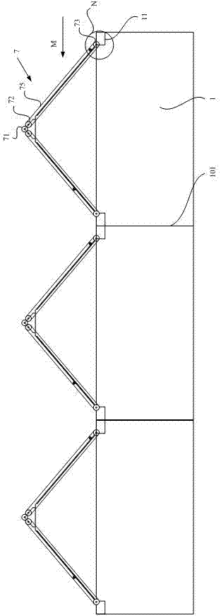
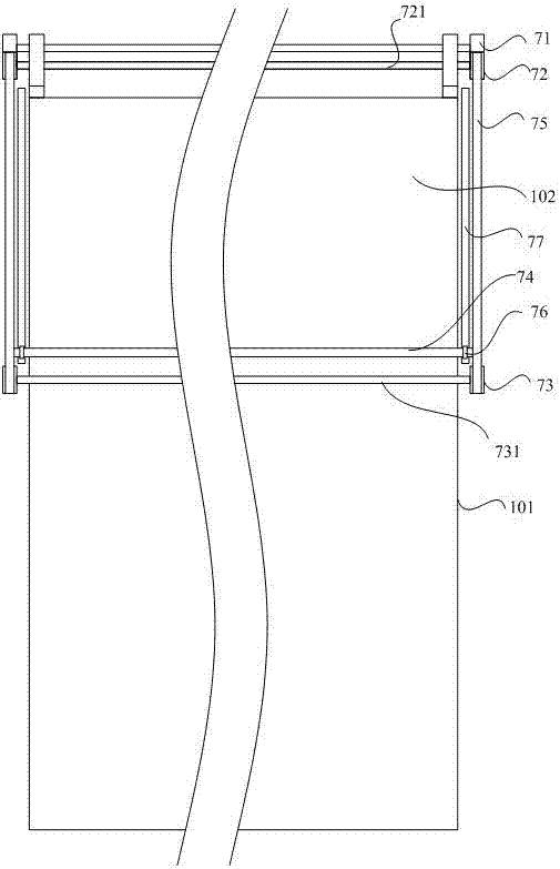
[0033] Such as Figure 1-Figure 3 As shown, the driving mechanism includes a motor 71, two upper synchronous wheels 72 and two lower synchronous wheels 73, an upper synchronous lever 721 is arranged between the two upper synchronous wheels 72, and an upper synchronous lever 721 is arranged between the two lower synchronous wheels 73. A lower synchronous rod 731 is provided, and a synchronous connector 75 is provided between the upper synchronous wheel 72 and the corresponding lower synchronous wheel 73. The synchronous connector 75 is provided with a mounting seat 751, and the mounting seat 751 is A shaft hole is provided, and the film roll shaft 74 is arranged between the two mounts 75 and is rotatably installed in the shaft hole. The rotating part 76 that drives the roll film shaft to rotate, and a matching part 77 for cooperating with the rotating part 76 is also provided between the upper synchronizing wheel 72 and the corresponding lower synchronizing wheel 73; the upper ...

Embodiment 2

[0036] Such as Image 6 As shown, the drive mechanism includes a motor, a rotating shaft 71, a drive chain 72 and a take-up reel 73, the film roll shaft 74 is provided with a rotatable sleeve 741, and one end of the drive chain 72 is connected to the sleeve 741 , the other end of the driving chain 72 is connected to the winding reel 73, the motor 71 is drivingly connected to the rotating shaft 71, the rotating shaft 71 is provided with a driving sprocket 711, and the driving sprocket 711 is connected to the rotating shaft 71. The drive chain 72 is engaged. Specifically, the rotating shaft 71 is located between the film winding shaft 74 and the winding reel 73, and the motor drives the rotating shaft 71 to rotate, so that the driving sprocket 711 pulls the film winding shaft 74 to move through the drive chain 72, thereby cooperating with the rotating part 76 and the matching part 77 , to realize the rotation of the film roll shaft 74. Wherein, the film roll shaft 74 can also ...

Embodiment 3

[0038] Based on the above technical solutions, optional, such as Figure 7-Figure 8 As shown, the greenhouse system of this embodiment also includes a water supply pipe 2, the lower installation surface of the greenhouse 1 is the ground reference plane A, and also includes a water collection container 3; the top of the greenhouse 1 is formed with a plurality of sunken water collection tanks 11 , the water collection tank 11 is respectively connected with the water collection container 3, the water supply pipe 2 is connected with the water collection container 3; the lower edge of the greenhouse 1 is provided with an annular water blocking enclosure 4, and the annular blocking The upper part of the water enclosure 4 is located above the ground reference plane A, the lower part of the annular water blocking enclosure 4 is located below the ground reference plane A, and the water supply pipe 2 is located below the ground reference plane A And lower than the annular water blocking...


PUM


Abstract

The invention discloses a greenhouse system and a greenhouse plantation method. The greenhouse system comprises a supporting frame and a first greenhouse film arranged on the supporting frame. The greenhouse system is characterized by also comprising a film rolling mechanism, wherein the film rolling mechanism comprises a film rolling shaft for rolling the first greenhouse film, and a driving mechanism which drives the film rolling shaft to move; the film rolling shaft is provided with a rotation part used for converting linear movement into rotary movement to drive the film rolling shaft to rotate; the supporting frame is also provided with a cooperation part used for cooperating with the rotation part to drive the rotation part to rotate; the lower edge of the first greenhouse film is arranged on the film rolling shaft. The greenhouse system is automatically started in a large range, and the quality of agricultural products is improved.

Description

technical field [0001] The invention relates to the technical field of agricultural engineering, in particular to a greenhouse system and a greenhouse planting method. Background technique [0002] At present, the greenhouse planting technology is widely promoted, wherein the adopted greenhouse generally consists of a supporting frame and a greenhouse film, and the greenhouse film is supported by the supporting frame to form a greenhouse. In the actual use of greenhouses, ventilation is usually carried out to meet the growth requirements of crops. General greenhouses will set vents according to needs. For example: Chinese Patent No. 201520789494.6 discloses a greenhouse, which uses a cylinder to drive the cover to move up and down. Ventilation; Chinese Patent No. 201320260498.6 discloses an automatic ventilation device for greenhouses, which uses a linear motor to drive the vent membrane switch covered on the vent; Chinese Patent No. 201520222282.X discloses a time-controlle...

Claims


Application Information

Patent Timeline
Patent Type & Authority Applications(China)
IPC IPC(8): A01G9/24E03B3/02
CPCA01B79/02A01G9/14A01G9/1438A01G9/241A01G9/247A01G22/05E03B3/02Y02A20/108Y02A40/25
Inventor 秦春明秦晓汉
Owner 秦春明
Why Eureka
Try Eureka