Robot end clamping module driven by steering engine

A steering gear drive and robot technology, applied in the direction of chucks, manipulators, manufacturing tools, etc., can solve the problems of large volume, high cost, and cumbersome control of the clamping module, and achieve simple structure, reduce intermediate transmission links, and small volume Effect

Inactive Publication Date: 2017-08-15
GUANGDONG UNIV OF TECH
View PDF6 Cites 15 Cited by
  • Summary
  • Abstract
  • Description
  • Claims
  • Application Information

AI Technical Summary

Problems solved by technology

[0005] The main purpose of the present invention is to propose a robot end clamping module driven by a steering gear with simple structure, small size, compact size and flexible operation, aiming to solve the problem of excessive volume, high cost and relatively poor control of the clamping module in the prior art. cumbersome technical issues to improve the application range of clamping modules in robots

Method used

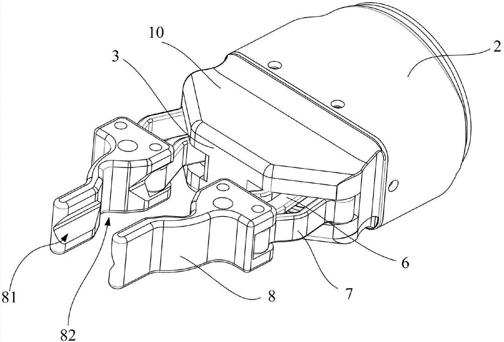
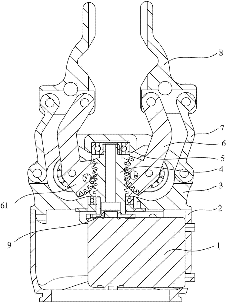
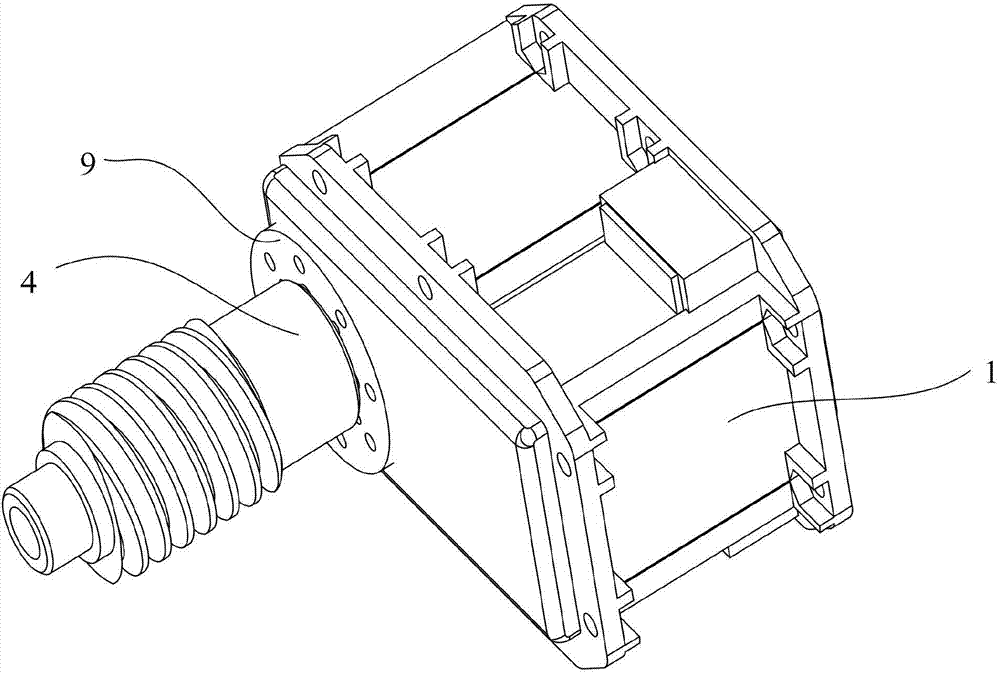

Image

  • Robot end clamping module driven by steering engine
  • Robot end clamping module driven by steering engine
  • Robot end clamping module driven by steering engine

Examples


Embodiment Construction

[0027] The following will clearly and completely describe the technical solutions in the embodiments of the present invention with reference to the accompanying drawings in the embodiments of the present invention. Obviously, the described embodiments are only part of the embodiments of the present invention, not all of them. Based on the embodiments of the present invention, all other embodiments obtained by persons of ordinary skill in the art without creative efforts fall within the protection scope of the present invention.

[0028] It should be noted that if there is a directional indication (such as up, down, left, right, front, back...) in the embodiment of the present invention, the directional indication is only used to explain the position in a certain posture (as shown in the accompanying drawing). If the specific posture changes, the directional indication will also change accordingly.

[0029] In addition, if there are descriptions involving "first", "second" and ...


PUM


Abstract

The invention discloses a robot end clamping module driven by a steering engine. The end clamping module comprises the drive steering engine capable of outputting power outwards. The power output end of the drive steering engine is connected with a steering engine output disc. The other end of the steering engine output disc is connected with one end of a worm arranged in an upper base and drives the worm to rotate forwards or backwards. A pair of drive clamping arms is further hinged into the upper base in a bilateral symmetry mode. The worm is in engaged transmission connection with the drive clamping arms, so that the drive clamping arms swing around the hinge center of the upper base. The clamping ends of the drive clamping arms can be reunited or separated. Compared with the prior art, the robot end clamping module driven by the steering engine has the advantages of being simple in structure, small in size, compact, flexible to operate and the like; control under conditions of various torque, speeds and positions can be achieved by controlling the steering engine motion mode; and a lower base is of a replaceable structure, and can cooperate with ends of different robots for operation quite conveniently, so that a work procedure needing to prevent workpieces from being damaged during clamping is efficiently completed.

Description

technical field [0001] The invention relates to the technical field of steering gear type robot clamping, in particular to a robot end clamping module driven by a steering gear. Background technique [0002] In industrial production, it is often necessary to carry out workpiece sorting, handling and other processes. When the above-mentioned processes are carried out by manpower, workers can easily use different forces to perform corresponding operations through their own judgment, so manual methods are not easy to cause damage to the workpiece. However, if workers engage in such simple and repetitive work for a long time, it is easy to make workers feel disgusted with the work, and as the domestic birth rate gradually declines, labor costs will continue to rise. Therefore, through industrial upgrading, the use of robots to replace some simple and repetitive tasks is in line with the trend of social development. [0003] When robots replace part of human work, the action of ...

Claims


Application Information

Patent Timeline
Patent Type & Authority Applications(China)
IPC IPC(8): B25J15/02
CPCB25J15/0213
Inventor 管贻生李坚王秀谷世超苏满佳
Owner GUANGDONG UNIV OF TECH
Why Eureka
Try Eureka