

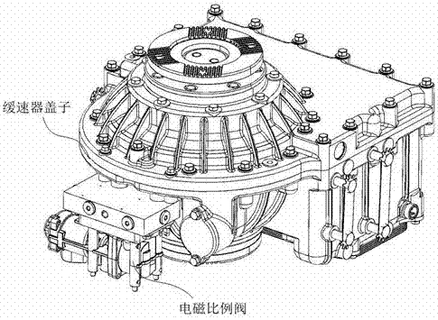
Air inlet channel structure of hydraulic retarder venting device
A hydraulic retarder and ventilation device technology, applied in the direction of liquid resistance brakes, brake types, mechanical equipment, etc., can solve the problems of air leakage into the working chamber and affect the work of the hydraulic retarder, so as to increase the service life And performance, the effect of media oil recovery promotion
- Summary
- Abstract
- Description
- Claims
- Application Information
AI Technical Summary
Problems solved by technology
Method used
Image

Examples
Embodiment 1
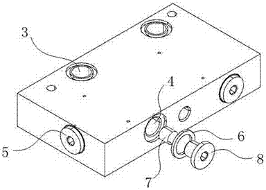
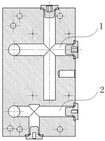
[0019] like Figure 1-3 As shown, the present invention discloses an air inlet structure of a hydraulic retarder ventilator. The ventilator is a rectangular structure, and the upper surface of the ventilator is provided with two sets of circular openings connected with the hydraulic retarder shell. There are two sets of circular openings connected to the electromagnetic proportional valve on the lower surface, several circular openings are opened on the side of the ventilation device, two sets of air inlets are arranged in the ventilation device, and the upper The circular openings on the surface and the circular openings on the sides communicate with each other to form an airway structure.
[0020] The air inlets are respectively a group of cross-shaped structure air inlets 1 and a group of T-shaped structure air inlets 2. The air inlets all use circular openings on the upper surface of the ventilation device as air inlets 3, and the air inlets on the side of the ventilation ...
PUM
 Abstract
Description
Claims
Application Information