Cutting device

A cutting device, cutting fluid technology, applied in the direction of electrical components, semiconductor/solid-state device manufacturing, circuits, etc., can solve the problems of maintaining productivity, inability, cutting chips sticking to the workpiece, etc., to prevent halo. Effect

Active Publication Date: 2017-08-15
DISCO CORP
View PDF7 Cites 3 Cited by
  • Summary
  • Abstract
  • Description
  • Claims
  • Application Information

AI Technical Summary

Problems solved by technology

However, with this method, since it takes time to remove the cutting fluid, it is not possible to maintain sufficiently high productivity.
In addition, there are also problems such as the chips generated during cutting sticking to the workpiece due to excessive blowing air.

Method used


Image

  • Cutting device
  • Cutting device
  • Cutting device

Examples


Embodiment Construction

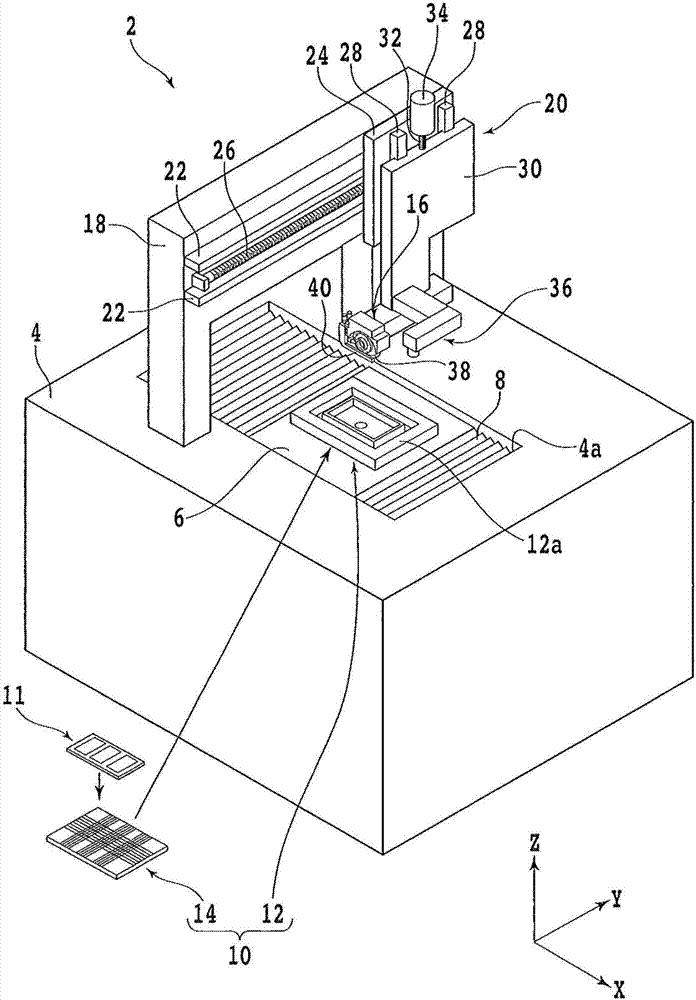
[0020] An embodiment of one aspect of the present invention will be described with reference to the drawings. figure 1 It is a perspective view schematically showing a configuration example of the cutting device of the present embodiment. Such as figure 1 As shown, the cutting device 2 has a base 4 that supports each structure.

[0021] A rectangular opening 4 a long in the X-axis direction (front-rear direction, machining feed direction) is formed on the upper surface of the base 4 . In this opening 4a, an X-axis moving table 6, an X-axis moving mechanism (not shown) for moving the X-axis moving table 6 in the X-axis direction, and a dust-proof and anti-dust mechanism for covering the X-axis moving mechanism are provided. Drop cover8.

[0022] The X-axis moving mechanism has a pair of X-axis guide rails (not shown) parallel to the X-axis direction, and the X-axis moving table 6 is slidably mounted on the X-axis guide rails. A nut portion (not shown) is provided on the low...


PUM


Abstract

The invention provides a cutting device. The cutting device 2 is provided with a retaining working bench 10 used to retain a processed object 11. The retaining working bench comprises a retaining tool 14 and a tool base 12. The retaining tool is provided with a retaining surface 14a, which is used to retain the processed object; a plurality of retracting grooves 14c used for the cutting tool, which are disposed on the position of the segmentation predetermined line 19 of the processed object retained by the retaining surface; a plurality of absorption holes 14d, which are disposed in the various areas divided by the retracting grooves of the cutting tool. The tool base is provided with a negative pressure transmission part 12b, which is used to transmit negative pressure to the absorption holes; a carrying part (12a), which is used to carry the retaining tool. The retaining tool is provided with a plurality of cutting liquid overflow grooves 14e, which are adjacent to the retracting grooves used for the cutting tool in a corresponding way, and are provided with bottom surfaces 14g lower than the bottom surfaces 14f of the retracting grooves used for the cutting tool.

Description

technical field [0001] The present invention relates to a cutting device used for cutting a workpiece such as a package substrate. Background technique [0002] For example, a package substrate in which a plurality of semiconductor chips is sealed with resin or the like is cut with a cutting tool along a planned dividing line called a street, and the package substrate is divided into a plurality of package devices corresponding to each semiconductor chip. When cutting a workpiece such as the package substrate, the workpiece may be held using a specially designed holding jig (for example, refer to Patent Document 1). [0003] The holding jig is provided with, for example, a plurality of undercut grooves for cutting tools corresponding to the planned dividing line of the workpiece, and a plurality of suction holes for sucking each region of the workpiece divided by the planned dividing line. Using this holding jig, the workpiece can be cut while being sucked and held in the a...

Claims


Application Information

Patent Timeline
Patent Type & Authority Applications(China)
IPC IPC(8): H01L21/304H01L21/683
CPCH01L21/3043H01L21/3046H01L21/6838H01L21/78B26D7/018B26D7/088H01L21/76H01L22/12
Inventor 佐胁悟志山铜英之
Owner DISCO CORP
Why Eureka
Try Eureka