
Dust removing device used for power distribution cabinet, and low-voltage power distribution cabinet

A technology of dust removal device and power distribution cabinet, applied in the field of low voltage power distribution cabinet and dust removal device, can solve the problems of poor dust removal method of low voltage power distribution cabinet, no solution proposed, unfavorable ventilation and heat dissipation, etc., so as to improve the poor dust removal method. Effect

Inactive Publication Date: 2017-08-15
重庆汉嘉电气股份有限公司
View PDF5 Cites 5 Cited by
  • Summary
  • Abstract
  • Description
  • Claims
  • Application Information

AI Technical Summary

Problems solved by technology

In the existing technology, most of the manual dust removal is used regularly. However, the problem with this method is that when the internal dust has accumulated to a certain concentration and has not been manually removed, it is very easy to gather on the ventilation holes, which is seriously unfavorable for ventilation and heat dissipation. Adverse Effects of Dust on Power Distribution Devices
[0004] Aiming at the problem of poor dust removal methods of low-voltage power distribution cabinets in the above-mentioned prior art, no effective solution has been proposed yet

Method used


Image

  • Dust removing device used for power distribution cabinet, and low-voltage power distribution cabinet
  • Dust removing device used for power distribution cabinet, and low-voltage power distribution cabinet
  • Dust removing device used for power distribution cabinet, and low-voltage power distribution cabinet

Examples


Embodiment 1

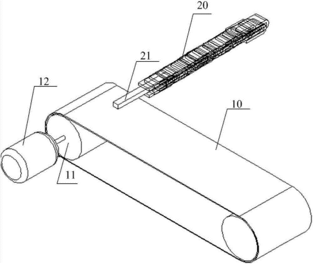
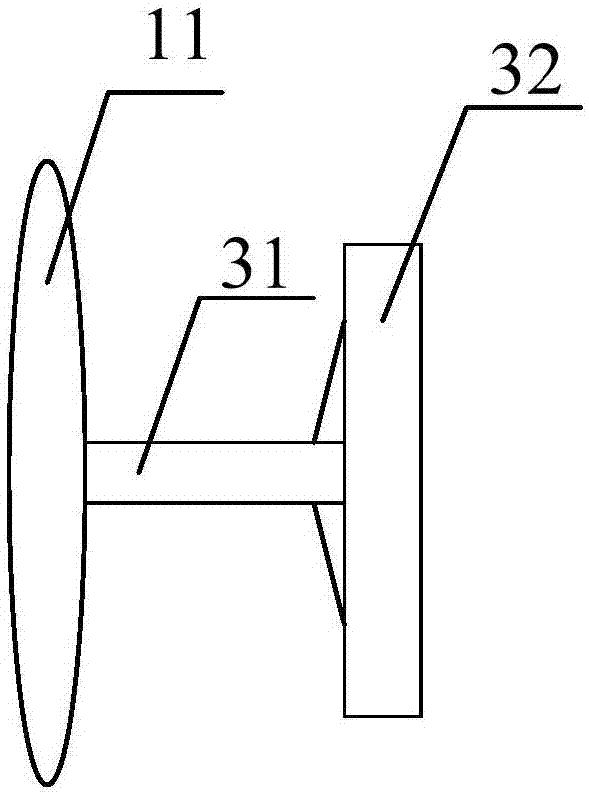
[0043] This embodiment provides a dust removal device for power distribution cabinets, see figure 1 A schematic structural diagram of a dust removal device for a power distribution cabinet is shown, including: a transmission mechanism, a dust removal tool, and a controller; the transmission mechanism includes: a transmission belt 10, a bearing 11 that drives the transmission belt to run, and a motor 12 that drives the bearing to rotate; , the length of the transmission belt is greater than the side length of the ventilation area composed of multiple ventilation holes in the power distribution cabinet; there is also a fixing piece at the center of the bearing to fix the transmission mechanism inside the power distribution cabinet; the motor is also equipped with a motor fixing frame , one end of the motor fixing frame is used to engage the motor, and the other end of the motor fixing frame is used for fixed connection with the power distribution cabinet; the ventilation area is ...

Embodiment 2

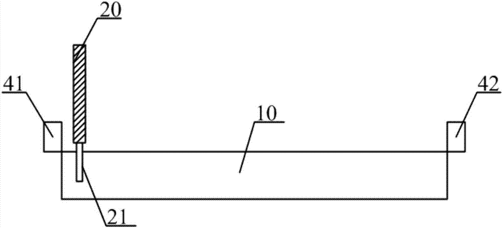
[0056] In the foregoing embodiments, the controller controls the rotation direction, rotation speed and duration of the motor according to the set period and the rotation mode of the motor. This embodiment provides another implementation mode in which the controller controls the operation of the motor , the dust removal device also includes a first contact sensor and a second contact sensor respectively set up at both ends of the transmission belt; the first contact sensor and the second contact sensor are both connected to the controller;

[0057] The first contact sensor is used to send a first signal to the controller when the dust removal tool is touched; the second contact sensor is used to send a second signal to the controller when the dust removal tool is touched;

[0058] The controller is used for controlling the rotation direction of the motor according to the first signal and the second signal.

[0059] For a clear understanding of the positional relationship, see ...

Embodiment 3

[0062] There are many ways to start the dust removal device. The first is to start regularly according to the preset cycle, the second is to start by manual control, and the third is to start automatically according to the dust concentration in the cabinet; the above forms are different. There are unique advantages, which can be used at the same time, or one of them can be selected.

[0063] The first two methods will not be described in detail. In order to enable the dust removal device to realize the third startup method, the dust removal device also includes a dust sensor connected to the controller. The dust sensor is used to collect dust concentration parameters and send the dust concentration parameters to the controller. ; The controller is also used to automatically start the motor to rotate when the dust concentration parameter is greater than the set threshold.

[0064] Through the above method, the dust removal device can remove dust in time to achieve an effective ...


PUM


Abstract

The invention provides a dust removing device used for a power distribution cabinet, and a low-voltage power distribution cabinet, which relate to the technical field of power distribution. The dust removing device comprises a transmission mechanism, a dust removing tool and a controller, wherein the transmission mechanism comprises a transmission belt, a bearing and a motor, the bearing drives the transmission belt to move, and the motor drives the bearing to rotate; a fixed member is arranged at the center of the bearing; the motor is equipped with a motor fixing frame; the dust removing tool comprises a dust removing main body and a connecting part; the dust removing main body is used for removing dust of a ventilation region, one end of the connecting part is connected with the dust removing main body, and the other end is connected to the transmission belt, so that the dust removing main body moves along with the movement of the transmission belt; and the controller is connected with the motor, and is used for controlling a rotating direction and rotating duration of the motor. The dust removing device can be used for removing dust of the ventilation region, in which dust is most liable to gather, of the power distribution cabinet, so as to prevent heat dissipation from being affected because the dust blocks the ventilation region, and the problem of poor effect of a low-voltage power distribution cabinet dust removing method in the prior art is effectively solved.

Description

technical field [0001] The invention relates to the technical field of power distribution, in particular to a dust removal device for a power distribution cabinet and a low-voltage power distribution cabinet. Background technique [0002] The low-voltage power distribution cabinet is a terminal equipment suitable for the power distribution system required by power plants, substations and major power customers. It can be used for power supply, lighting and power conversion, distribution and control of power distribution equipment. plays an important role in the system. [0003] Since there are many power distribution devices inside the low-voltage power distribution cabinet, in order to ensure the normal operation of the power distribution devices, it is necessary to have higher requirements for the working environment inside the power distribution cabinet. Among them, the dust concentration in the cabinet is the primary factor affecting the work of power distribution device...

Claims


Application Information

Patent Timeline
Patent Type & Authority Applications(China)
IPC IPC(8): H02B1/28B08B1/00
CPCH02B1/28B08B1/165B08B1/30B08B1/10B08B1/12
Inventor 王军邱添
Owner 重庆汉嘉电气股份有限公司
Learn More