Pressure control method in ventilator and cpap mode

A continuous positive pressure ventilation and ventilator technology, applied in the field of medical devices, can solve the problems of reducing fan power, unstable fan speed, and reducing user comfort, and achieve the goal of improving comfort, avoiding difficulty in exhalation, and avoiding pressure fluctuations. Effect

Active Publication Date: 2019-12-10
HUNAN MICOME ZHONGJIN MEDICAL SCI & TECH DEV CO LTD
View PDF4 Cites 2 Cited by
  • Summary
  • Abstract
  • Description
  • Claims
  • Application Information

AI Technical Summary

Problems solved by technology

For ventilators that do not use valves, it is difficult to maintain a stable pressure output in CPAP mode. In the prior art, PID is mainly used to adjust the pressure of the ventilator, that is, the ventilator monitors that the outlet pressure is lower than the set value. When the pressure is high, increase the fan power; when the pressure is high, reduce the fan power to restore the pressure to the set value
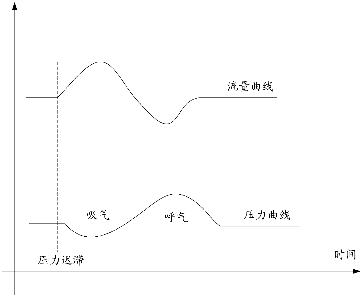
[0003] The above-mentioned method for regulating the pressure of the ventilator has the following disadvantages: the feedback delay is obvious, such as figure 2 As shown, it is usually necessary to wait until there is an obvious pressure change before adjusting the fan. In fact, the pressure has been further reduced when the fan is adjusted, and the pressure cannot be adjusted quickly, which is easy to cause shocks, resulting in unstable fan speed and user comfort. problems such as lowering

Method used


Image

  • Pressure control method in ventilator and cpap mode
  • Pressure control method in ventilator and cpap mode
  • Pressure control method in ventilator and cpap mode

Examples


Embodiment Construction

[0047] In order to make the object, technical solution and advantages of the present invention clearer, the present invention will be further described in detail below in conjunction with the accompanying drawings and embodiments. It should be understood that the specific embodiments described here are only used to explain the present invention, not to limit the present invention. Based on the embodiments of the present invention, all other embodiments obtained by persons of ordinary skill in the art without making creative efforts belong to the protection scope of the present invention.

[0048]It should be noted that the descriptions involving "first", "second", etc. in the present invention are only for descriptive purposes, and should not be understood as indicating or implying their relative importance or implicitly indicating the number of indicated technical features . Thus, the features defined as "first" and "second" may explicitly or implicitly include at least one ...


PUM


Abstract

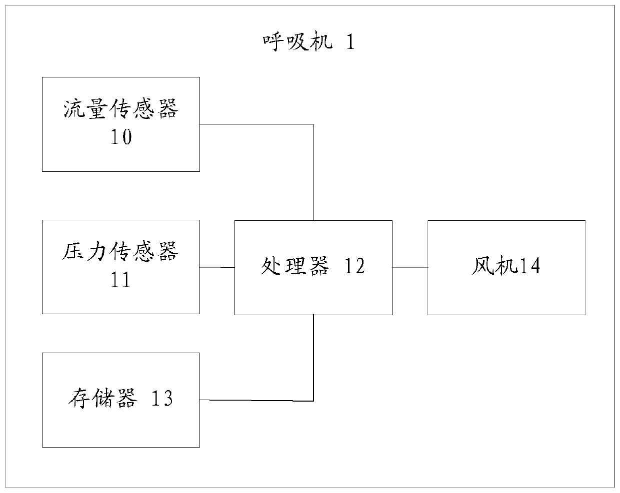
The invention relates to a respirator and a pressure control method in a continuous positive airway pressure (CPAP) mode. The respirator comprises a flow sensor, a pressure sensor, a processor, a memorizer, and a control program stored on the memorizer and capable of running on the processor. When the control program is executed by the processor, the method includes the following steps that when the respirator is in the CPAP mode, a flow curve and a pressure curve of the respirator are obtained, an inspiration initial moment P is determined, and the output power of a draught fan of the respirator is increased at the inspiration initial moment P; the change ratio of flow and the change ratio of pressure are obtained based on the flow curve and the pressure curve, and in the state that the change ratio of the flow is continuously larger than 0 and the change rate of the pressure is smaller than 0, the output power of the draught fan of the respirator is intermittently increased; in the state that the change rate of the pressure is larger than 0, the output power of the draught fan of the respirator is intermittently reduced. The pressure can be rapidly adjusted, the pressure is stably output, and the user comfort is improved.

Description

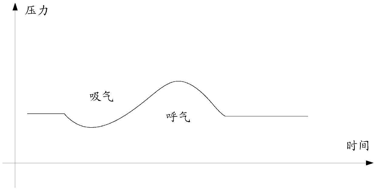
technical field [0001] The invention relates to the technical field of medical devices, in particular to a ventilator and a pressure control method in CPAP mode. Background technique [0002] When using a ventilator, the user's inhalation and exhalation will cause large fluctuations in the pressure of the ventilator, such as figure 1 As shown, the pressure curve will have a larger depression when the user inhales, and a larger bulge when the user exhales. For ventilators that do not use valves, it is difficult to maintain a stable pressure output in CPAP mode. In the prior art, PID is mainly used to adjust the pressure of the ventilator, that is, the ventilator monitors that the outlet pressure is lower than the set value. When the pressure is high, increase the power of the fan. When the pressure is high, reduce the power of the fan to restore the pressure to the set value. [0003] The above-mentioned method for regulating the pressure of the ventilator has the following...

Claims


Application Information

Patent Timeline
Patent Type & Authority Patents(China)
IPC IPC(8): A61M16/00G05D16/20
CPCA61M16/00A61M16/0003A61M2016/003A61M2205/3331G05D16/20
Inventor 戴征丁锦黄皓轩刘炜徐勤鹏
Owner HUNAN MICOME ZHONGJIN MEDICAL SCI & TECH DEV CO LTD
Why Eureka
Try Eureka