Oscillation cross section adjustable oscillator

An adjustable, oscillator technology, applied in shaking/oscillating/vibrating mixers, chemical instruments and methods, dissolution, etc., can solve problems such as poor oscillation of the vibrating frame, long oscillation time, and increased sliding resistance, and achieve Improve the homogenization efficiency of oscillation, improve the uniformity of oscillation, and increase the effect of oscillation area

Inactive Publication Date: 2017-08-18
周伟
View PDF1 Cites 4 Cited by
  • Summary
  • Abstract
  • Description
  • Claims
  • Application Information

AI Technical Summary

Problems solved by technology

Since the separatory funnel is fixedly installed on the separatory funnel positioning device during the oscillation homogenization process, the bottom of the separatory funnel is parallel to the bottom of the chassis, and the oscillation area of ​​the liquid to be oscillated is the cross-sectional area of ​​the diameter of the filling bottle, which actually participates in the oscillation The area is small and cannot be adjusted, which will inevitably lead to longer oscillation time
The main cause of high failure rate, short service life and poor reliability is that the structure of the guiding mechanism between the vibrating frame and the fixed frame is inconsistent. , a guide rod usually cooperates with three guide wheels, and the three guide wheels are respectively arranged on both sides of the guide rod, forming a three-point contact between the guide wheel and the guide rod. During the oscillation process, the guide rod is subjected to alternating pressure, The guide rod is deformed, which will increase the sliding resistance of the vibration frame up and down, and the vibration frame will not vibrate smoothly. If it is light, it will cause the vibration frequency to be unstable.

Method used


Image

  • Oscillation cross section adjustable oscillator
  • Oscillation cross section adjustable oscillator
  • Oscillation cross section adjustable oscillator

Examples


Embodiment 1

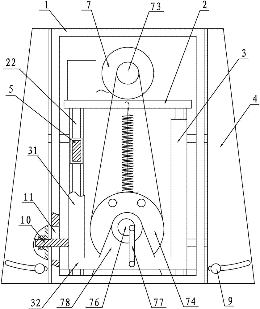
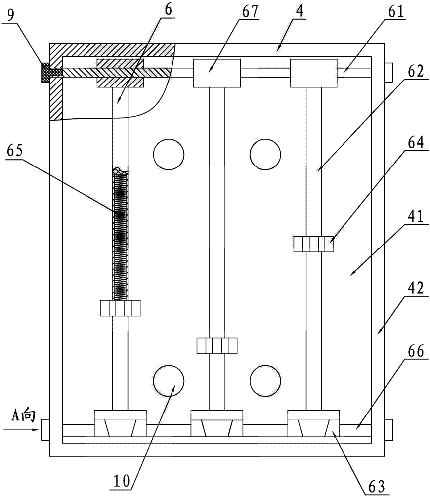
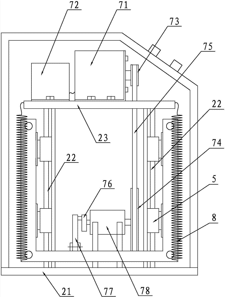
[0034] Embodiment 1: an oscillator with adjustable oscillation section, such as Figure 1 to Figure 6As shown, it includes a chassis 1, a fixed frame 2, an oscillating bracket 3, an oscillating box 4, a guide slider 5, a separating funnel positioning device 6, an oscillation generating mechanism 7 and a return spring 8, and the fixed frame 2 consists of a base 21, four A guide rail 22 and a fixed platen 23 are formed, and four guide rails 22 are fixed between the base 21 and the fixed platen 23 according to a rectangular distribution scheme, and the oscillation support 3 includes four vertical rods 31 and a rectangular bottom frame 32, two guide sliders 5 are fixed at intervals along the height direction on each vertical rod 31, and the guide sliders 5 are slidably set on the corresponding guide rails 22, and the oscillation generating mechanism 7 includes a motor 71 , frequency conversion regulator 72, driving wheel 73, driven wheel 74, belt 75, eccentric wheel 76, rocker lev...


PUM


Abstract

The invention provides an oscillation cross section adjustable oscillator. An up-down sliding mechanism comprising a guide slide rail and a guide slide block is adopted between an oscillation support and a fixed mount; and in a process of sliding up and down, the guide rail is free from external force, so that the running abrasion and the sliding friction resistance can be greatly reduced, defects of stress deformation and the like of a guide rod in the prior art can be eliminated, the operation is stable and reliable and the service life is long. A mounting column in a separating funnel positioning device can slide in an adjustment arc chute of an oscillation box along a lower rotary pin shaft, so that the mounting column is in an inclined state; an adjustment range of an angle of inclination is determined by an arc angle of the adjustment arc chute, so that to-be-oscillated bottle body liquid is properly tilted according to requirements of a tester, the surface area of the liquid stored in an actually oscillated bottle is increased, the oscillation uniformity of the to-be-oscillated liquid is improved, and the oscillation homogenization time is also reduced. A motor is controlled by avariable frequency electric actuator to ensure that the oscillation frequency can be changed, and the oscillator has a variable frequency and is efficient, energy-saving and reliable.

Description

[0001] Technical field: [0002] The invention relates to the technical field of experimental equipment, in particular to a separatory funnel oscillator with uniform oscillation and durability. [0003] Background technique: [0004] Separating funnels are widely used in various industries such as soil analysis, chemical testing, chemical experiments, food and water quality analysis. In the above practical application, it is usually necessary to oscillate and homogenize the test liquid stored in the separatory funnel. Therefore, people have designed various forms of oscillators according to the above requirements, so that the most used oscillators are currently the most effective. It is the technical solution provided by Chinese patent 200920235427.4. [0005] This patent discloses a novel separatory funnel oscillator, which includes a chassis, a lift frame, a separatory funnel positioning device, a power mechanism, a return spring, a guide mechanism and a control panel. The ...

Claims


Application Information

Patent Timeline
Patent Type & Authority Applications(China)
IPC IPC(8): B01F11/00
CPCB01F31/20B01F31/201B01F2101/23
Inventor 周伟任健张焘
Owner 周伟
Why Eureka
Try Eureka