

Angular oscillation centrifugal pump
a centrifugal pump and angular oscillation technology, applied in the direction of non-positive displacement pumps, non-positive displacement pumps, fluid engines, etc., can solve the problems of large overall size of turbopumps and adversely affect pump performance, and achieve the effect of simple structure suitable for miniaturization
- Summary
- Abstract
- Description
- Claims
- Application Information
AI Technical Summary
Benefits of technology
Problems solved by technology
Method used
Image

Examples
first embodiment
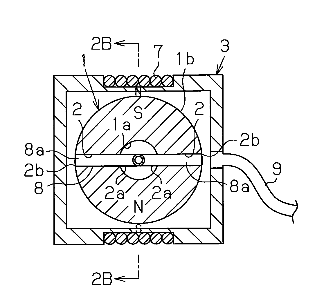
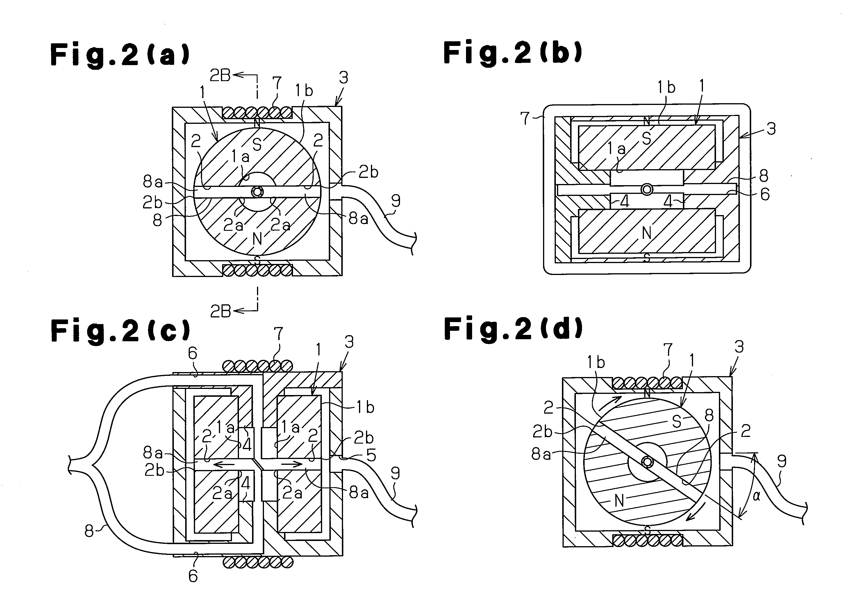
[0030]FIGS. 2(a) to 2(c) show an angular oscillation centrifugal pump that has a structure for causing the angular oscillator 1 to angularly oscillate. The centrifugal pump incorporates the resonance oscillation motor of Japanese Laid-Open Patent Publication No. 2007-289911.
[0031]The angular oscillator 1 is accommodated in a case 3, which is formed as a hollow box. The case 3 has a pair of bearing portions 4, which are partly located in the axial hole 1a of the angular oscillator 1 to rotatably support the angular oscillator 1. Contacting portions of the inner circumferential surface of the axial hole 1a and the outer circumferential surface of the bearing portions 4 are subjected to surface treatment so that the angular oscillator 1 smoothly performs angular oscillation.
[0032]The case 3 further has an outlet opening 5, to which a discharge pipe 9 is connected, and two suction openings 6, which extend from the outside of the case 3 to the axial hole 1a through the bearing portions ...
second embodiment
[0047]FIGS. 3(a) to 3(c) illustrate a centrifugal pump according to a
[0048]The hollow portion of a case 13 is cylindrical. That is, the case 13 has an inner circumferential surface 13a the size of which is substantially equal to that of the angular oscillator 1. The diameter of the case inner circumferential surface 13a is slightly greater than the outer diameter of the angular oscillator 1. To allow the case inner circumferential surface 13a to rotatably support the outer circumferential surface 1b of the angular oscillator 1, facing portions of these are subjected to mirror coating. That is, no structure like the bearing portions 4, which are partly located in the axial hole 1a of the angular oscillator 1, is required to allow the case inner circumferential surface 13a to function as a bearing as shown in FIG. 3(b). It is sufficient if a distal end 8a of the suction pipe 8 can supply fluid into the axial hole 1a of the angular oscillator 1.
[0049]Outlet openings 5 extend in the cir...
third embodiment
[0052]FIGS. 4(a) and 4(b) illustrate a centrifugal pump which has a simple structure.
[0053]A case 3 is formed by a rectangular frame-like inner case 3a and an outer case 3b, which hermetically accommodates the inner case 3a. An outlet opening 5 and a suction openings 6 are formed in the outer case 3b. The inner case 3a rotatably supports a hollow shaft 11 with a pair of bearings 4. An angular oscillator 1, which is a magnet of a first dipole, and through hole support arms 12 are attached to the hollow shaft 11 so as to rotate integrally. The through hole support arms 12 function as through hole accommodating arms that pass the clearance of the rectangular frame of the inner case 3a and extend in the radial direction, so as to project outward from the angular oscillator 1. The hole support arm 12 includes two radial through holes 2 that communicate with the axial hole 11a of the hollow shaft 11.
[0054]A suction pipe 8 is drawn from the outside to the inside of the outer case 3b, and ...
PUM
 Abstract
Description
Claims
Application Information