Injection device based on dual piezoelectric actuators

A spraying device and actuator technology, which is applied to the device and coating of the surface coating liquid, can solve the problems of low dispensing frequency and slow speed, and achieve high work efficiency, large driving force and accurate displacement. Effect

Active Publication Date: 2022-07-12
SHANDONG UNIV
View PDF7 Cites 0 Cited by
  • Summary
  • Abstract
  • Description
  • Claims
  • Application Information

AI Technical Summary

Problems solved by technology

[0005] The present invention is to solve the technical problem of low dispensing frequency and slow speed of the existing jet dispensing device driven by piezoelectric ceramic actuators, and provides a dual piezoelectric actuator based on high dispensing frequency and fast speed. spraying device

Method used


Image

  • Injection device based on dual piezoelectric actuators
  • Injection device based on dual piezoelectric actuators
  • Injection device based on dual piezoelectric actuators

Examples


Embodiment Construction

[0059] Hereinafter, the present invention will be further described in detail with specific embodiments with reference to the accompanying drawings.

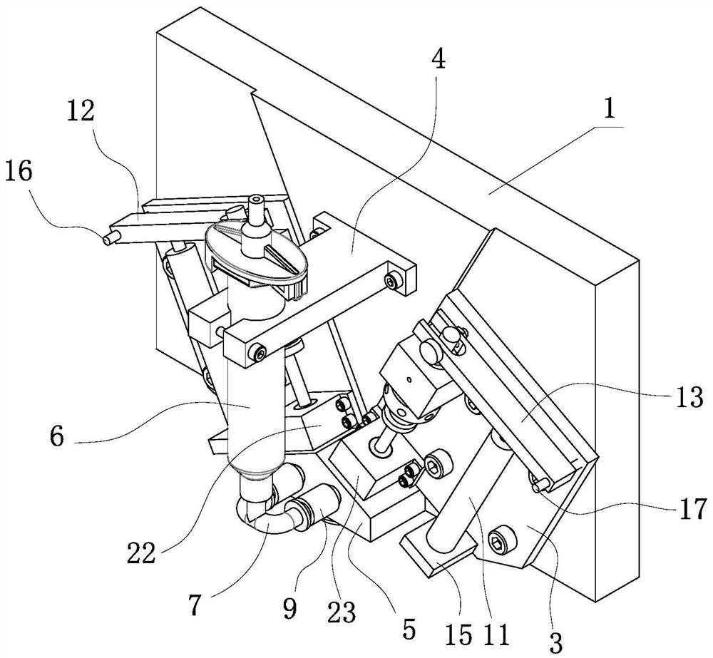
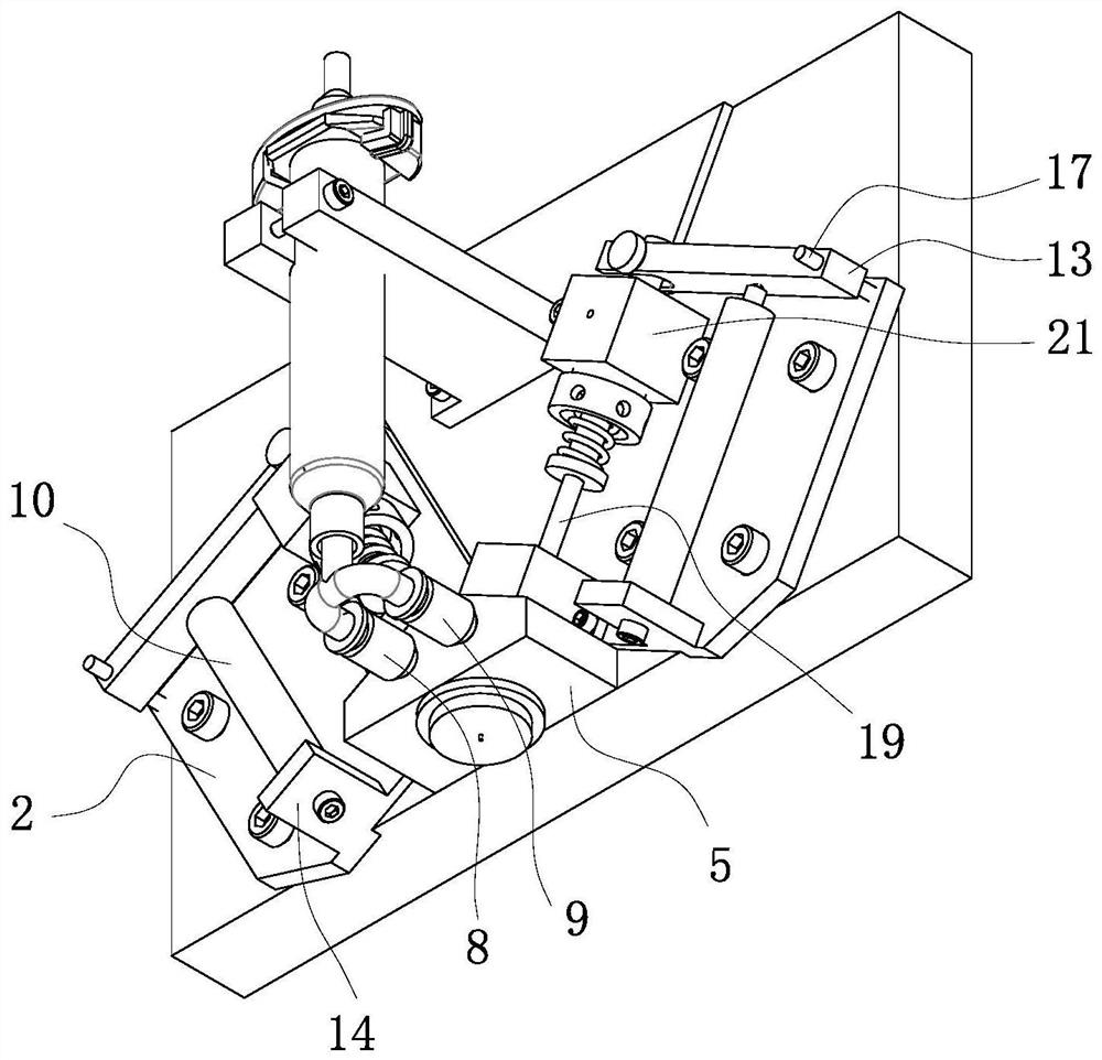
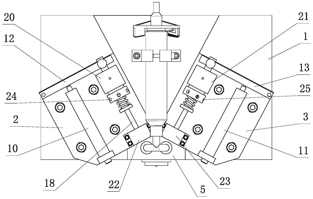
[0060] like Figure 1-7 , 15, the injection device based on dual piezoelectric actuators includes a rear seat 1, a left support plate 2, a right support plate 3, a rubber storage cylinder bracket 4, a triangular nozzle valve 5, a rubber storage cylinder 6, a rubber guide tube 7, Left joint 8, right joint 9, left piezoelectric ceramic actuator 10, right piezoelectric ceramic actuator 11, left link 12, right link 13, left shaft 16, right shaft 17, left striker 18, right striker 19. Upper left end cap 20, upper right end cap 21, lower left end cap 22, lower right end cap 23, left adjustment nut 24, right adjustment nut 25, left spring 26, right spring 27, upper left linear bearing 30, lower left linear bearing 31, The upper right linear bearing 32 and the lower right linear bearing 33 are provided.

[0061] The left support plate...


PUM


Abstract

The invention relates to a spray device based on a double piezoelectric actuator, which solves the technical problems of low dispensing frequency and slow speed of the existing spray type glue dispensing device driven by piezoelectric ceramic actuators. It includes two sets of symmetrically arranged striker-type injection mechanisms driven by piezoelectric ceramic actuators, and a triangular nozzle valve. There is an included angle between the two groups of striker-type injection mechanisms. The bottom surface of the triangular nozzle valve is connected with a nozzle, and the triangular nozzle valve There are left and right glue storage chambers symmetrically arranged inside, and the triangular nozzle valve is provided with a left glue guide cavity and a right glue guide cavity. The left glue guide cavity is connected with the left glue storage cavity, and the right glue guide cavity is connected with the right glue storage cavity. The cavity is connected, the nozzle is provided with a glue extrusion cavity, the bottom of the nozzle is provided with a nozzle that communicates with the glue extrusion cavity, the left glue storage cavity and the right glue storage cavity are respectively connected with the glue extrusion cavity, and the lower part of the left striker is located in the left glue storage cavity. , the lower part of the right striker is located in the right glue storage cavity. The present invention is widely used in glue dispensers.

Description

technical field [0001] The invention relates to a spray-type glue dispensing device, in particular, to a spray device based on a dual piezoelectric actuator. Background technique [0002] In the field of microelectronics technology, dispensing machines are commonly used equipment in electronic product processing and packaging. With the increasing complexity and miniaturization of integrated circuits, semiconductor packaging requires smaller dimensions, more leads, denser interconnects, etc., and the requirements for dispensing technology are getting higher and higher. At present, the commonly used jet dispensing technology based on high-frequency components such as piezoelectric ceramics, which drives the glue liquid distribution by the striker, uses the high-frequency vibration striker to drive the glue liquid to be ejected from the nozzle at a high speed, with fast response speed and small glue droplet volume. , The advantages of high distribution accuracy. This technolo...

Claims


Application Information

Patent Timeline
Patent Type & Authority Patents(China)
IPC IPC(8): B05C5/02B05C11/10
CPCB05C5/0225B05C11/1026Y02P70/10
Inventor 路士州东旭光李东琦单晓晖朱尘宇李琦周凤岐
Owner SHANDONG UNIV
Why Eureka
Try Eureka