
Automatic bucket holding device based on automatic positioning

An automatic positioning and displacement technology, applied in the field of trash can cleaning, can solve problems such as slippage, slippage of the outer wall of the trash can, slipping of the trash can, etc., and achieve the effect of meeting large batches, facilitating standardization, and locking stability

Pending Publication Date: 2017-08-18
YANGZHOU JINWEI ENVIRONMENTAL PROTECTION TECH CO LTD
View PDF11 Cites 1 Cited by
  • Summary
  • Abstract
  • Description
  • Claims
  • Application Information

AI Technical Summary

Problems solved by technology

[0005] However, there is inevitably a big disadvantage in the bucket-holding scheme: when the trash can needs to be clamped and turned over after the trash can is cleaned, the cleaning liquid will inevitably remain on the surface of the trash can. The outer wall of the trash can is very slippery, and the outer wall of the trash can is irregular. Therefore, when the trash can is clamped, there will be relative sliding between the clamping unit and the outer wall of the trash can, resulting in insufficient clamping. barrel slip
[0006] Even the surface of the trash can may have oily pollutants before cleaning, and the outer wall of the trash can itself is relatively smooth. The traditional clamping method is not reliable enough, and there will still be slippage during multiple clamping operations

Method used


Image

  • Automatic bucket holding device based on automatic positioning
  • Automatic bucket holding device based on automatic positioning
  • Automatic bucket holding device based on automatic positioning

Examples


Embodiment Construction

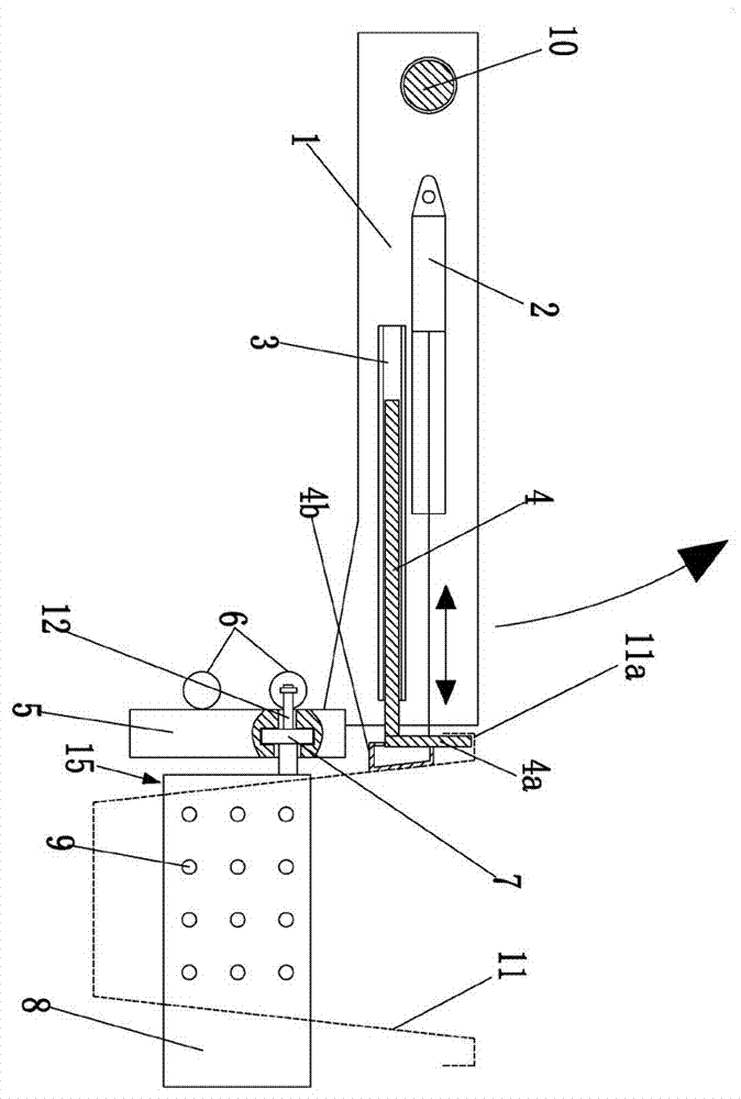
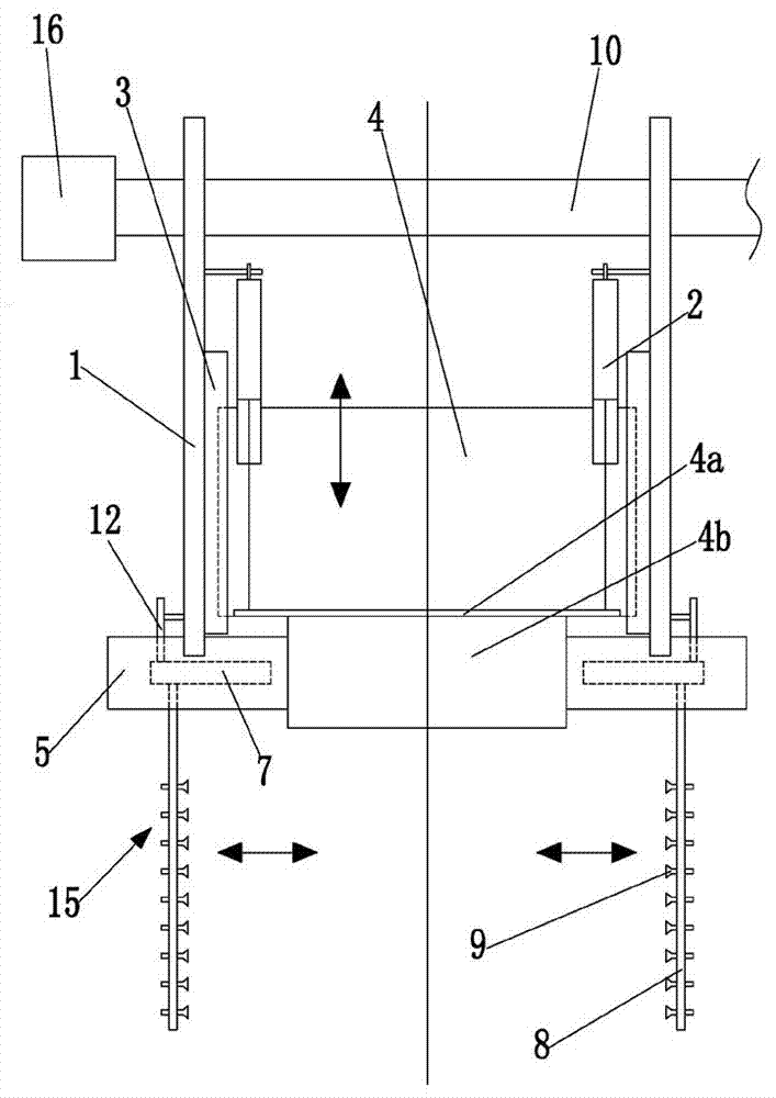
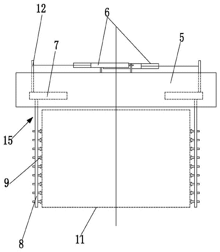
[0022] to combine figure 1 , 2 As shown, an automatic barrel holding device based on automatic positioning includes a rotary drive mechanism 16, an overturning main shaft 10 controlled by the rotary drive mechanism 16, an overturning frame 1 mounted on the overturning main shaft 10, and a The clamping unit of the trash can 11 arranged on the flip frame 1 also includes a negative pressure adsorption unit, a vacuum generator 14 connected with the negative pressure adsorption unit, and an automatic positioning mechanism for limiting the position of the trash can 11 .

[0023] The above-mentioned clamping unit includes a clamping seat 5 fixed on the flip frame 1, and also includes a pair of clamping seats 5 that are oppositely arranged on the clamping seat 5 and are used to hug the outer wall of the trash can 11 and are movable on the clamping seat 5. The movable clamping part 15 and the negative pressure adsorption unit are installed on the two movable clamping parts 15 cooperat...


PUM


Abstract

The invention discloses an automatic bucket holding device based on automatic positioning in the technical field of garbage bucket washing. The automatic bucket holding device comprises a rotation driving mechanism, an overturning main shaft, an overturning support and a holding unit, and further comprises a negative pressure adsorption unit, a vacuum generator and an automatic positioning mechanism; the holding unit comprises a clamping base and a pair of movable clamping parts oppositely arranged on the clamping base, and the negative pressure adsorption unit is controlled by the vacuum generator to generate negative pressure so that an garbage bucket outer wall can be attracted; the automatic positioning mechanism comprises a deflection air cylinder, a displacement guide rail and a movable limiting base, the movable limiting base is installed on the displacement guide rail in a sliding manner, a cylinder barrel of the deflection air cylinder is hinged to the overturning support, and a piston rod of the deflection air cylinder is hinged to the movable limiting base; and a bucket hooking plate used for hooking the bucket edge of the garbage bucket is arranged on the movable limiting base. Slippage of the garbage bucket in the clamping and overturning process can be thoroughly prevented, any damage to the garbage bucket is avoided, and the clamping effect is stable and reliable.

Description

technical field [0001] The invention relates to the technical field of garbage can cleaning, in particular to an automatic bucket holding device. Background technique [0002] At present, trash can cleaning equipment has begun to be widely used in the market, because trash can cleaning equipment can clean trash cans in a centralized manner, and the cleaning efficiency is very high, and it plays an irreplaceable role in municipal engineering. In the trash can cleaning process, the first step is to clamp the trash can and turn it over to the cleaning station, and the last step is to clamp the cleaned trash can and turn the trash can out. The first step and If the last step can be successfully completed, the smoothness of the entire trash can cleaning operation can be guaranteed. [0003] The original scheme of clamping the trash can in the industry is to use the upper and lower chucks to clamp the side of the bucket, so as to complete the clamping. Although the clamping effec...

Claims


Application Information

Patent Timeline
Patent Type & Authority Applications(China)
IPC IPC(8): B08B9/42B08B9/44
CPCB08B9/42B08B9/44B08B2209/08
Inventor 陈彪冯卫民陈忠陈宏飞许雷刘玉红
Owner YANGZHOU JINWEI ENVIRONMENTAL PROTECTION TECH CO LTD
Learn More