Eureka AIR delivers breakthrough ideas for toughest innovation challenges, trusted by R&D personnel around the world.

Continuous casting production line of foamed aluminium

A technology for casting production and foaming aluminum, which is applied in foundry workshops, casting equipment, pig iron casting workshops, etc., can solve the problems of inability to realize fully automated assembly line operation of foamed aluminum and aluminum ingots, and low degree of automation, so as to reduce labor costs, The effect of improving production quality and increasing production speed

Inactive Publication Date: 2017-08-18
长兴鼎盛机械有限公司
View PDF1 Cites 4 Cited by
  • Summary
  • Abstract
  • Description
  • Claims
  • Application Information

AI Technical Summary

Benefits of technology

This patented technology allows for efficient use of heat energy during metal manufacturing processes while improving productivity rates or reducing costs associated therewith. It involves combining two different types of equipment together through an agitation/displacement process before pouring the metallic material onto another casting machine's casting lines. By doing these steps multiple times per unit time, the overall efficiency can be increased compared to traditional methods where only one step was done once. Additionally, the system uses a combination of pumping devices and pushers to achieve complete fluidization without leaving any residue behind inside the casting machines themselves. Overall, this new method simplifies the entire cycle of producing foamed Al products efficiently and minimizing manual effort required.

Problems solved by technology

This patented technical problem addressed in this patents relates to improving the efficiency and accuracy during producing foams containing various types of chemical substances like bone powder (Pb) and ceramic powders. Current methods require multiple steps involving different equipment and involve laborious processes requiring highly skilled operators who have limited their ability to perform these tasks accurately without sacrificially damaging any parts they may wear out overtime due to frequent use.

Method used


Image

  • Continuous casting production line of foamed aluminium
  • Continuous casting production line of foamed aluminium
  • Continuous casting production line of foamed aluminium

Examples


Embodiment 1

[0079] The embodiments are described below with reference to the accompanying drawings. The embodiments shown below do not limit the invention content described in the claims. required for the solution.

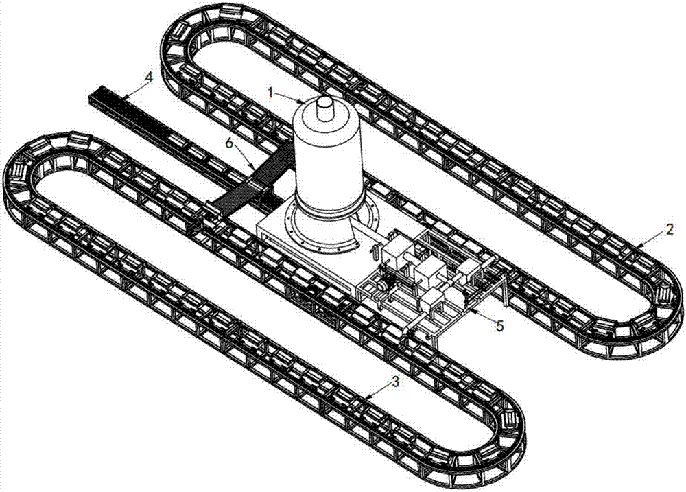
[0080] Such as figure 1 As shown, a foamed aluminum continuous casting production line, including a hot melting furnace 1, also includes:

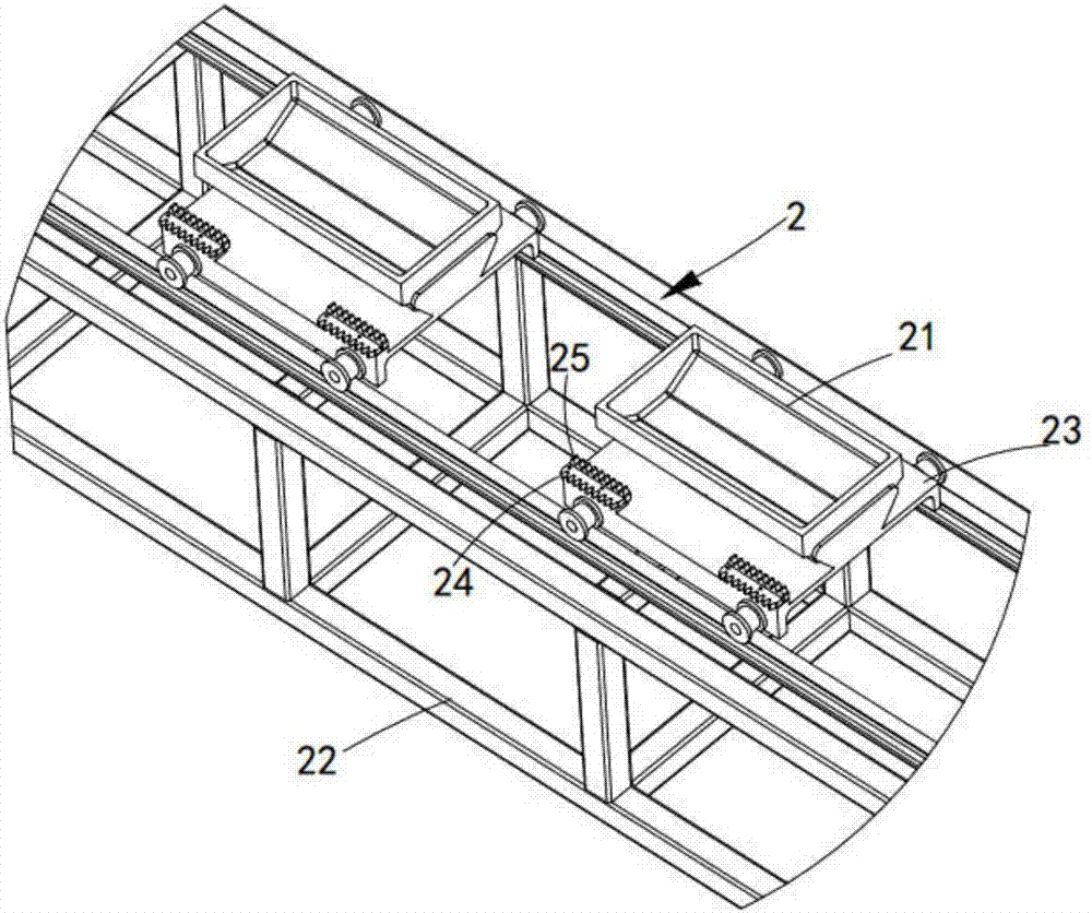
[0081] The first casting line 2, the first casting line 2 is arranged on one side of the hot melting furnace 1, which is arranged in a ring shape, and a plurality of first casting aluminum molds 21 are arranged equidistantly along its length direction on it, the first casting aluminum mold 21 A casting aluminum mold 21 is used to carry aluminum liquid and cast aluminum ingot 7;

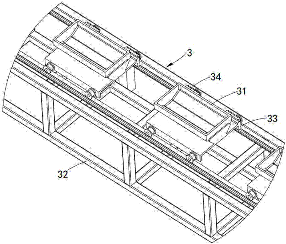
[0082] The second casting line 3, the second casting line 3 is arranged on the other side of the hot melting furnace 1 relative to the first casting line 2, which is arranged in a ring shape, and is equidistantly arranged along its length direction Several sec...

Embodiment 2

[0149] Figure 20 It is a structural schematic diagram of Embodiment 2 of a foamed aluminum continuous casting production line of the present invention; as Figure 20 As shown, the parts that are the same as or corresponding to those in Embodiment 1 use the reference numerals corresponding to Embodiment 1. For the sake of simplicity, only the differences from Embodiment 1 will be described below. This embodiment two and figure 1 The difference of the shown embodiment one is:

[0150] Such as Figure 20 As shown, a foamed aluminum continuous casting production line also includes:

[0151] The heat preservation device 8, the heat preservation device 8 is located in front of the stirring and discharging device 5, it is located between the first casting line 2 and the second casting line 3, and it is used for the first casting aluminum mold 21 Carry out heating insulation with the second casting aluminum mold 31;

[0152] Air-cooling device 9, described air-cooling device 9 ...


PUM


Abstract

The present invention provides a continuous casting production line for foamed aluminum, which arranges a ring-shaped first casting line and a second casting line on both sides of a hot melting furnace, so that the first casting aluminum mold and the second casting aluminum mold on it can be Circulating flow, and automatic liquid injection of the first casting aluminum mold and the second casting aluminum mold through the stirring and discharging device, and foamed aluminum and aluminum ingots can be cast, and the first casting The foamed aluminum ingot cast by the aluminum mold and the second casting aluminum mold is pushed to the aluminum ingot output line for automatic output, which solves the technical problem of full-time casting of the foamed aluminum and aluminum ingot and realizes the foamed aluminum and aluminum ingot casting process The molten aluminum in the furnace is melted to the foamed aluminum casting until the automatic output of the foamed aluminum and aluminum ingots is fully braked.

Description


Claims


Application Information

Patent Timeline
Owner 长兴鼎盛机械有限公司
Why Eureka
Eureka Blog
Learn More