Clamp and mechanical arm

A fixture and clamping technology, applied in metal processing machinery parts, clamping, clamping devices, etc., can solve problems such as excellent clamping function, and achieve the effects of simple structure, convenient operation and high use efficiency

Pending Publication Date: 2017-08-18
NINGBO ZEE AUTOMATION EQUIP
View PDF4 Cites 2 Cited by
  • Summary
  • Abstract
  • Description
  • Claims
  • Application Information

AI Technical Summary

Problems solved by technology

[0005] In view of this, the object of the present invention is to provide a clamp and a manipulator to alleviate the technical problems that the clamps in the prior art cannot simultaneously have simple structure, convenient operation and excellent clamping function

Method used


Image

  • Clamp and mechanical arm
  • Clamp and mechanical arm
  • Clamp and mechanical arm

Examples


Embodiment 1

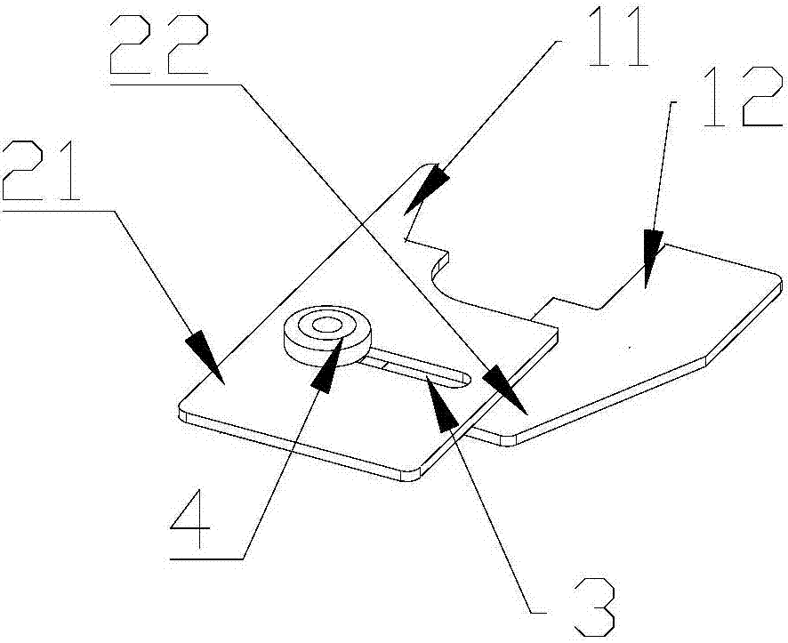
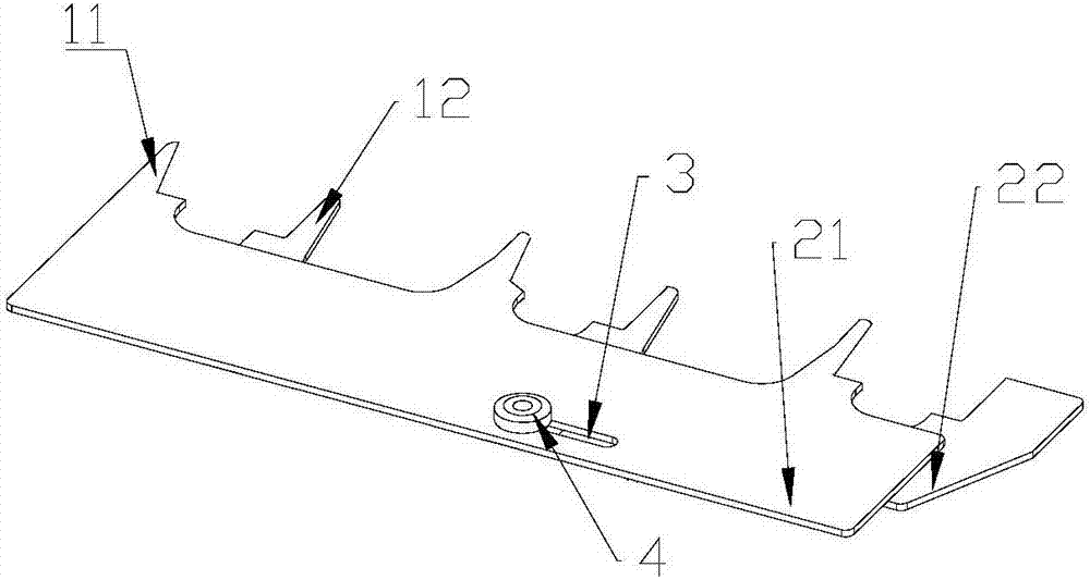
[0033] A kind of manipulator provided by the embodiment of the present invention, such as figure 1 As shown, including: clamping part and sliding part, wherein,

[0034] The clamping part includes an upper clamping area 11 and a lower clamping area 12 which are oppositely arranged;

[0035] The sliding part includes an upper sliding area 21 and a lower sliding area 22 arranged in layers, the upper sliding area 21 is connected to the upper clamping area 11, and the lower sliding area 22 is connected to the lower clamping area 12;

[0036] The upper sliding area 21 is provided with an adjustment hole 3, and the lower sliding area 22 is provided with a lower block, the lower block, the lower block is connected with a connecting rod, and the connecting rod passes through the adjustment hole 3 and is connected with a locking member 4, wherein , the connecting rod can slide along the adjusting hole 3, the locking part 4 can rotate relative to the connecting rod, and the rotation of...

Embodiment 2

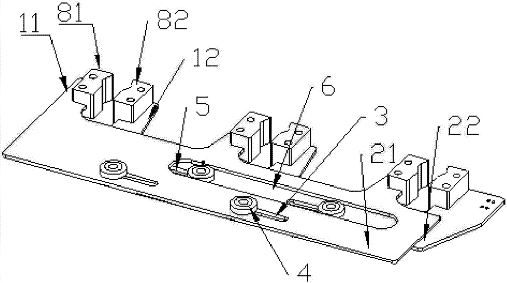
[0053] A manipulator provided in an embodiment of the present invention includes: a driving assembly and any clamp provided in Embodiment 1. like Figure 4 As shown, the drive assembly includes an upper drive assembly and a lower drive assembly, wherein the upper drive assembly is used to drive the movement of the upper sliding area 21 of the clamp, and the lower drive assembly is used to drive the movement of the lower slide area 22 of the clamp.

[0054] It should be noted, Figure 4 What is shown is only the situation that the manipulator includes a kind of clamp in the first embodiment.

[0055] In the embodiment of the present invention, the clamping part includes an upper clamping area 11 and a lower clamping area 12 arranged oppositely, and the workpiece to be processed is clamped between the upper clamping area 11 and the lower clamping area 12; The upper sliding area 21 and the lower sliding area 22, the upper sliding area 21 is connected with the upper clamping are...


PUM


Abstract

The invention provides a clamp and a mechanical arm, and relates to the technical field of machining auxiliary equipment. The clamp comprises a clamping part and a sliding part, the clamping part comprises an upper clamping area and a lower clamping area which are oppositely arranged, the sliding part comprises an upper sliding area and a lower sliding area which are stacked, the upper sliding area is connected with the upper clamping area, the lower sliding area is connected with the lower clamping area, the upper sliding area is provided with an adjusting hole way, the lower sliding area is provided with a lower clamping block, the lower clamping block is connected with a connecting rod, the connecting rod penetrates the adjusting hole way to be connected with a locking component, the connecting rod can slide along the adjusting hole way, the locking component can rotate relative to the connecting rod, and rotation of the locking component relative to the connecting rod enables the connecting rod to begin to or stop sliding on the adjusting hole way. The aim of tightly clamping workpieces with different sizes to be machined is achieved, and the problems that in the prior art, the clamp cannot achieve clamping and low cost at the same time are solved.

Description

technical field [0001] The invention relates to the technical field of mechanical processing auxiliary equipment, in particular to a clamp and a manipulator. Background technique [0002] When processing a workpiece on a machine tool, in order to make the surface of the workpiece meet the technical requirements such as the size and geometric shape specified in the drawing or the accuracy of its position with other surfaces, the workpiece must be clamped and positioned before processing. The manipulator is to achieve this function. main components. The manipulator is usually composed of a fixture base, a positioning element, a tool setting guide element, a fixture, a connecting element, etc. Among them, the positioning element is used to determine the correct position of the workpiece in the fixture, and the tool setting guide element is used to determine the relative position of the workpiece and the tool. The fixture is a component that directly clamps the workpiece. [0...

Claims


Application Information

Patent Timeline
Patent Type & Authority Applications(China)
IPC IPC(8): B23Q3/06B23Q3/08
CPCB23Q3/061B23Q3/08B23Q2703/04
Inventor 刘建军马盈丰
Owner NINGBO ZEE AUTOMATION EQUIP
Why Eureka
Try Eureka