Method for Operating a Work Station and a Work Station

A station and motion technology, applied in the directions of transportation and packaging, textile and papermaking, and conveying filamentous materials, etc., can solve the problems of high cost, damage to productivity, and time-consuming, and achieve the effect of simplifying equipment and improving productivity.

Active Publication Date: 2017-08-18
RIETER INGOLSTADT GMBH
View PDF5 Cites 6 Cited by
  • Summary
  • Abstract
  • Description
  • Claims
  • Application Information

AI Technical Summary

Problems solved by technology

In this case, the design of the mounting of the suction nozzle required for this is very complex and requires high control expenditure.
Furthermore, the movement of the suction nozzle is time-consuming and impairs the productivity of the workstation

Method used


Image

  • Method for Operating a Work Station and a Work Station
  • Method for Operating a Work Station and a Work Station
  • Method for Operating a Work Station and a Work Station

Examples


Embodiment Construction

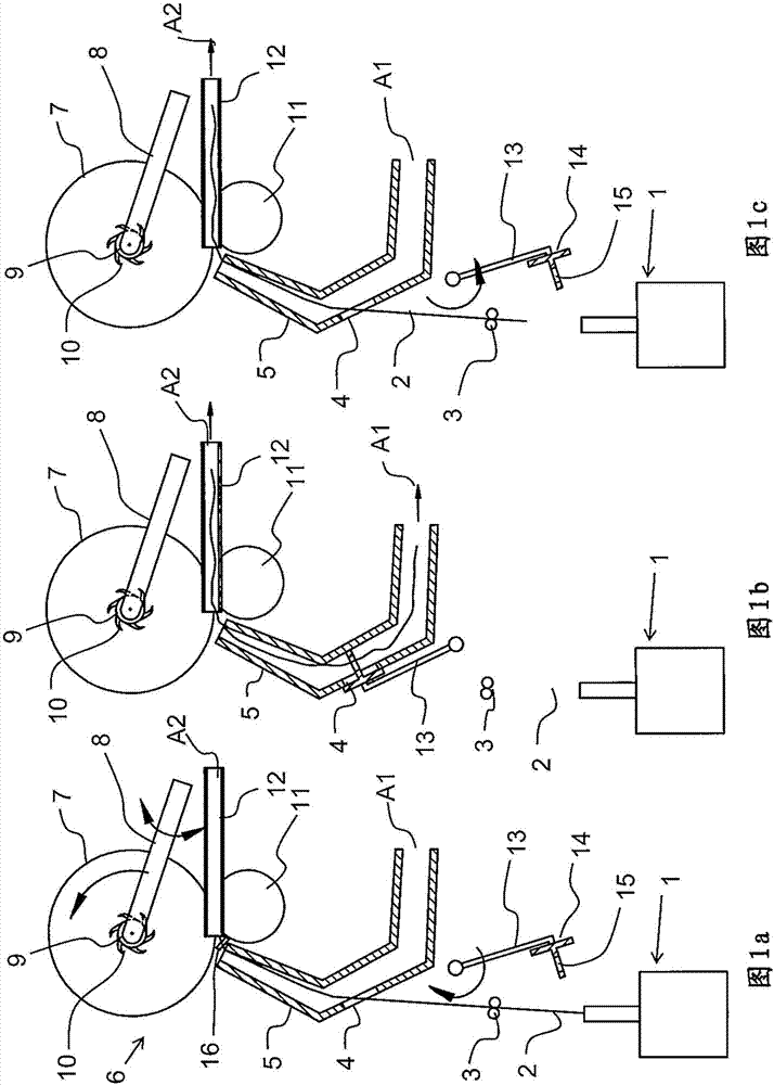
[0039] In Fig. 1a to Fig. 1c there is shown a roughly drawn side view of a spinning machine / winder, such as a rotor spinning machine or an open-end spinning machine, in which two a nozzle. The following exemplary embodiments relate accordingly to catch devices which are equipped with toothed bobbin holders. The capture device located on the bobbin or between the bobbin and the bobbin seat works according to the following description. In this case, the positioning of the yarn relative to the catching device can be modified so that the corresponding catching device can catch the yarn well and reliably.

[0040] In Fig. 1a the spinning / winding machine during production is shown. A yarn 2 is produced in a spinning device 1 and is withdrawn from the spinning device 1 by means of a driven take-off roller 3 . The yarn 2 travels through the opening 4 of the first suction nozzle 5 through the first suction nozzle 5 and to the winding device 6 . The winding device 6 has a bobbin 7 o...


PUM


Abstract

The invention provides a method for operating a work station and a work station. The work station has a spinning device or a head for delivering a thread along with a winding device for producing a cross wound package on a sleeve, wherein the winding device features a package holder with a package plate for receiving the sleeve and for catching a thread, a powered winding roller for rotating the sleeve and / or the package along with a thread traversing device. The work station is equipped with a first suction nozzle and a second suction nozzle. The thread is arranged for attachment on an empty sleeve in the two suction nozzles, and is stretched between in particular by means of negative pressure. Subsequently, the thread stretched between the two suction nozzles is captured by a catching device, in order to catch the thread and subsequently wind it onto the sleeve. With a corresponding work station, the two suction nozzles are arranged at each other in such a manner that the thread may be arranged for the attachment to an empty sleeve in the two suction nozzles and may be stretched between the two suction nozzles by means of negative pressure in at least the second suction nozzle in such a manner that the stretched thread can be captured between the two suction nozzles by a catching device, in order to catch the thread and subsequently wind it onto the sleeve.

Description

technical field [0001] The invention relates to a method for operating a station of a spinning machine and / or winder with a spinning device for producing yarn or bobbins for supplying yarn and for Winding device for producing cross-wound bobbins on a tube, wherein the winding device has a bobbin holder mounted in a pivotable manner, a driven winding drum (Spulwalze) for rotating the bobbin or bobbin, and a yarn traverse device, the bobbin holder has a bobbin tray seat for accommodating the bobbin and catching the yarn, and the station is equipped with a first suction nozzle directed towards the periphery of the bobbin and a second suction nozzle arranged at The bobbin tray is on the side facing away from the cross-wound bobbin and is directed substantially towards and spaced from the first suction nozzle. The invention also relates to corresponding stations of the spinning machine and / or winding machine. Background technique [0002] A method for operating a station of an ...

Claims


Application Information

Patent Timeline
Patent Type & Authority Applications(China)
IPC IPC(8): B65H67/08
CPCB65H67/08B65H2701/31B65H65/00B65H67/04D01H9/04B65H54/22B65H51/10B65H51/16B65H54/30D01H9/02
Inventor M·马莱克T·格鲁伯罗宾·维茵克里斯汀·凯特纳
Owner RIETER INGOLSTADT GMBH
Why Eureka
Try Eureka