

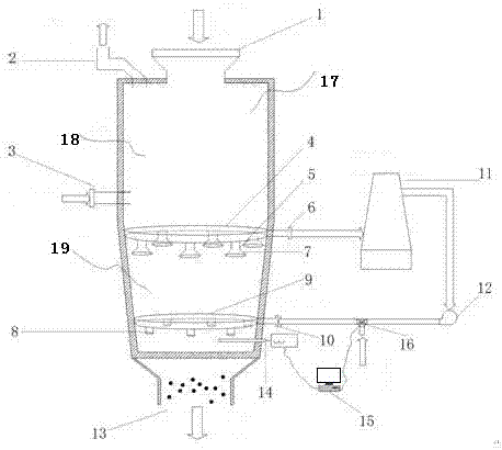
Cooling gas system for cooling section of shaft furnace
A cooling gas and cooling section technology, applied in the field of metallurgy, can solve the problems of unreasonable layout, low utilization rate of cooling gas, uneven distribution, etc. Effect
- Summary
- Abstract
- Description
- Claims
- Application Information
AI Technical Summary
Problems solved by technology
Method used
Image

Examples
Embodiment 1
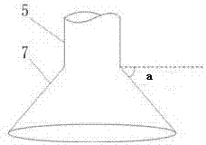
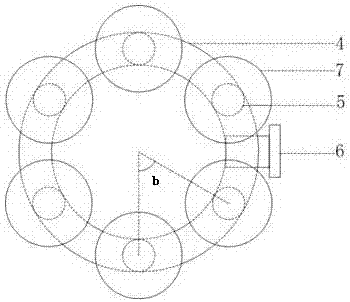
[0057] A test shaft furnace for direct reduction of iron oxide pellets, the pressure in the furnace is 0.18MPa(G), the inner diameter of the furnace in the cooling section is 1.5 meters, and the height of the cooling section is 2.5 meters. The cooling air inlet ring pipe is located 0.3m above the upper discharge valve, with an inner diameter of 15cm and 8 air inlets; An air receiving hood is welded on the air port, the angle between the side tangent of the air receiving hood and the horizontal is 45°, and the diameter of the air receiving hood is 40cm.
[0058] The cooling air water washing tower is 5 meters high and the inner diameter is 2 meters. The cooling air enters the tower from the lower part of the tower, and the cooling water enters the water washing tower from the upper part. ℃. The cooled air after water washing enters the secondary compressor, and the pressure is raised to 0.2MPa(G) and sent to the shaft furnace to be used again for cooling the sponge iron in the...
Embodiment 2
[0060] A test shaft furnace for direct reduction of iron oxide pellets, the pressure in the furnace is 0.18MPa(G), the inner diameter of the furnace in the cooling section is 2 meters, and the height of the cooling section is 3 meters. The cooling air inlet ring pipe is located 0.3m above the upper discharge valve, with an inner diameter of 20cm and 10 air inlets; An air receiving hood is welded on the air port, the angle between the side tangent of the air receiving hood and the horizontal is 60°, and the diameter of the air receiving hood is 45cm.
[0061] The cooling air water washing tower is 6 meters high and the inner diameter is 2 meters. The cooling air flows into the tower from the lower part of the tower, and the cooling water flows into the water washing tower from the upper part. ℃. The cooled air after water washing enters the secondary compressor, and the pressure is raised to 0.2MPa(G) and sent to the shaft furnace to be used again for cooling the sponge iron i...
PUM
 Abstract
Description
Claims
Application Information