Parking device and system

A technology of parking device and parking system, which is applied in the direction of buildings, building types, and buildings where cars are parked, and can solve problems such as difficulties in assembly, transportation, and movement, mutual influence of upper and lower parking spaces, and large amount of manufacturing materials. Assembling and transporting, parking operation is independent, and the effect of ensuring the carrying capacity

Pending Publication Date: 2017-08-18
NINGBO TOOLSIR ELECTROMECHANICAL CO LTD
View PDF6 Cites 2 Cited by
  • Summary
  • Abstract
  • Description
  • Claims
  • Application Information

AI Technical Summary

Problems solved by technology

[0003] At present, most of the three-dimensional composite parking spaces are in the form of double-layers without avoidance. The bottom parking spaces have no vehicle-carrying platform, and the vehicles can directly enter and exit freely. Driving in or out of the car, the equipment with this structure on the market has the disadvantages of complex mechanical structure and cumbersome operation
[0004] There is also a double-layer avoidance compound parking space equipment that is more common. Its structure is that multiple bottom platforms share a set of guide rails to realize the left and right translation of the parking spaces. Driven by the lifting drive system, the lifting movement is realized. When the lower parking space is in use and it is necessary to drive the car into or out of the upper parking space, the cars on the lower level must move along the guide rails in turn, so that the front of the upper level car to be driven out The lower parking space is vacated, and then the upper parking platform is landed; the parking equipment with this structure has the disadvantages of low space utilization, mutual influence of the upper and lower parking spaces, and complicated operation.
[0005] In addition, the existing parking equipment uses a solid whole plate to make the vehicle carrying platform, which not only causes the parking equipment to be heavy, but also makes its assembly, transportation and movement difficult, and inevitably leads to a large amount of manufacturing materials and high cost Shortcomings

Method used


Image

  • Parking device and system
  • Parking device and system
  • Parking device and system

Examples


Embodiment 1

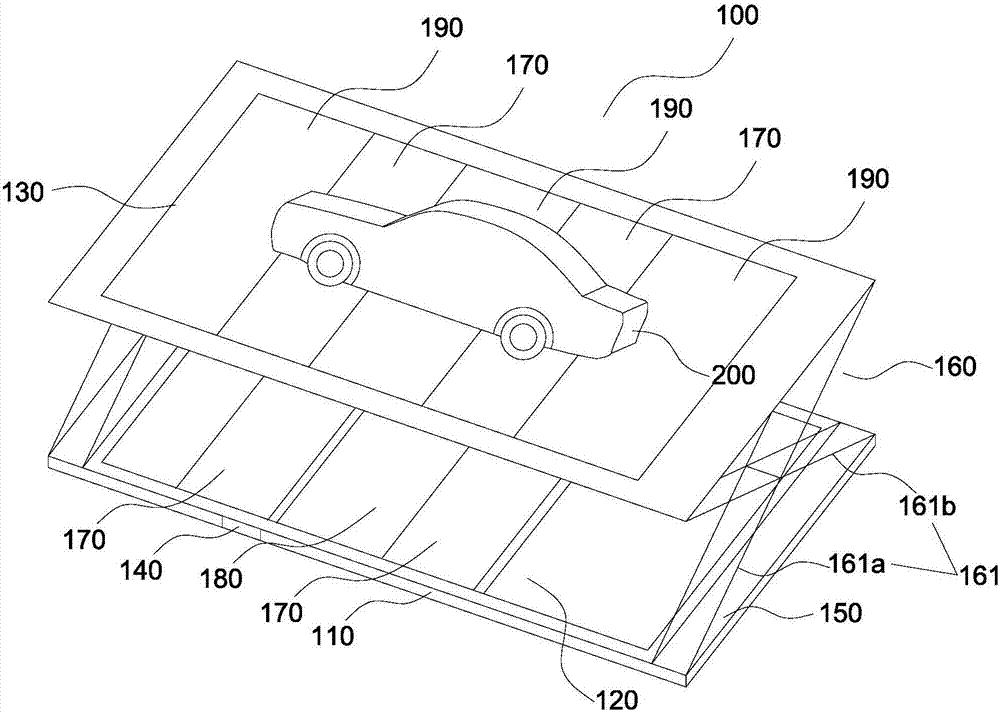
[0049] figure 1 Schematic structure of the parking device 100 provided for this embodiment Figure 1 .

[0050] A parking device 100, comprising a base 110 and a parking platform, the parking platform is a foldable structure, including a bottom parking platform 120 mounted on the base 110, and an upper part above the bottom parking platform 120 mounted on the base 110 Parking platform 130 ; the upper parking platform 130 can move laterally relative to the base 110 to move away from or approach the base 110 , and the upper parking platform 130 can vertically lift relative to the base 110 to fold or unfold. The base 110 is connected to the upper parking platform 130 through a lifting mechanism 160, and the lifting mechanism 160 includes a lifting rod 161 (including lifting rods 161a, 161b).

[0051] On the bottom parking platform 120 and / or the upper parking platform 130, two wheel support structures 170 are arranged corresponding to the positions of the wheels of the automobi...

Embodiment 2

[0068] The difference between this embodiment and the first embodiment lies in the arrangement of the wheel support structure.

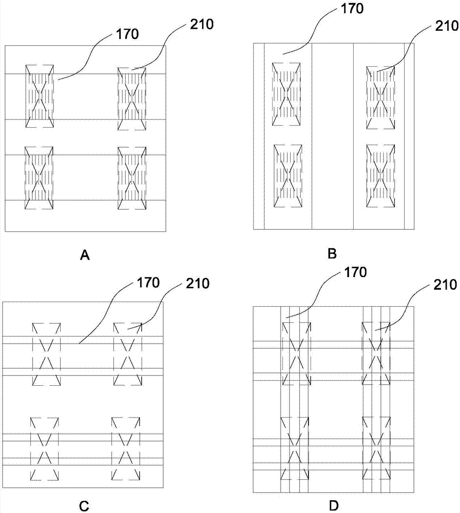
[0069] Figure 4 A schematic diagram of the location of the wheel support structure on the parking platform provided in this embodiment.

[0070] In this embodiment, the wheels are carried by four sets of wheel support bars 170 according to the number of wheels. The first wheel support bar and the second wheel support bar form the front wheel support structure, and the third wheel support bar and the fourth wheel support bar form the rear wheel support structure.

[0071] see Figure 4 As shown in Figures A and B, the first wheel support bar, the second wheel support bar, the third wheel support bar and the fourth wheel support bar all have two support arms, and the two support arms are directly installed on the The base of the parking platform or the upper frame of the upper parking platform is used to carry the wheels.

[0072] It is also possi...

Embodiment 3

[0087] refer to Figure 8-10 .

[0088] Figure 8-9 Two structural schematic diagrams of the preferred vertical lifting mechanism 150, Figure 10 It is a structural schematic diagram of the first lateral sliding mechanism 150 connected with the base 110 and the vertical lifting mechanism 160 .

[0089] Such as figure 1 , the parking device 100 further includes a circuit control device 140 , and a first lateral sliding mechanism 150 and a vertical lifting mechanism 160 disposed between the upper parking platform 130 and the base 110 . Wherein, the base 110 is set on a support surface, which can be the ground, floor slab or other column and plate structures, for supporting the parking device 100 ; the bottom parking platform 120 is installed on the base 110 . The base 110 is symmetrically provided with two first chutes, each of which is provided with a lateral sliding mechanism and a vertical lifting mechanism, and the upper parking platform 130 passes through the first late...


PUM


Abstract

The invention provides a parking device and system and belongs to the technical field of stereo parking equipment. The parking device comprises a base and a parking platform. The parking platform is of a foldable structure and comprises a bottom parking platform body on the base and at least one layer of upper parking platform body mounted above the base and located above the bottom parking platform bodies. Each layer of the at least one layer of upper parking platform body can move horizontally relative to the base to be far from or close to the base and can conduct lifting vertically relative to the base to be folded or unfolded. A plurality of wheel supporting structures corresponding to wheels are arranged on the bottom parking platform body and the upper parking platform bodies. At least one spacing area is arranged among the wheel supporting structures. Vehicles are borne by the wheel supporting structures. The parking device and system are suitable for being operated alone by a user, the necessary bearing capacity is guaranteed while the steel using amount is reduced, and economy and reliability are achieved.

Description

technical field [0001] The invention relates to the technical field of three-dimensional parking equipment. Background technique [0002] The rapid increase in the number of cars has made the land use in the city more and more tense, especially in many built residential quarters, office areas and leisure service areas, there are not enough parking spaces to meet user requirements. Therefore, the car parking place begins to evolve from a plane parking space to a three-dimensional compound parking space. At present, the three-dimensional composite parking space equipment has become an effective technical solution to solve the shortage of parking spaces. [0003] At present, most of the three-dimensional composite parking spaces are in the form of double-layers without avoidance. The bottom parking spaces have no vehicle-carrying platform, and the vehicles can directly enter and exit freely. Driving in or out of the car, the equipment with this structure on the market has the...

Claims


Application Information

Patent Timeline
Patent Type & Authority Applications(China)
IPC IPC(8): E04H6/04E04H6/06
CPCE04H6/04E04H6/06
Inventor 马宇尘
Owner NINGBO TOOLSIR ELECTROMECHANICAL CO LTD
Why Eureka
Try Eureka