Parking device, system and method

A technology of parking device and parking platform, which is applied to buildings, building types, buildings, etc. where cars are parked, can solve the problems of low space utilization rate of parking equipment, mutual influence of upper and lower parking spaces, and complex mechanical structure, so as to improve user experience. , The effect of independent parking operation and reasonable bearing structure

Pending Publication Date: 2017-02-22
NINGBO TOOLSIR ELECTROMECHANICAL CO LTD
View PDF0 Cites 4 Cited by
  • Summary
  • Abstract
  • Description
  • Claims
  • Application Information

AI Technical Summary

Problems solved by technology

[0004] At present, most of the three-dimensional composite parking spaces are in the form of double-layers without avoidance. The bottom parking spaces have no vehicle-carrying platform, and the vehicles can directly enter and exit freely. Driving in or out of the car, the equipment with this structure on the market has the disadvantages of complex mechanical structure and cumbersome operation
[0005] There is also a double-layer avoidance compound parking space equipment that is more common. Its structure is that multiple bottom platforms share a set of guide rails to realize the left and right translation of the parking spaces. Driven by the lifting drive system, the lifting movement is realized. When the lower parking space is in use and it is necessary to drive the car into or out of the upper parking space, the cars on the lower level must move along the guide rails in turn, so that the front of the upper level car to be driven out The lower parking space is vacated, and then the upper parking platform is landed; the parking equipment with this structure has the disadvantages of low space utilization, mutual influence of the upper and lower parking spaces, and complicated operation.

Method used


Image

  • Parking device, system and method
  • Parking device, system and method
  • Parking device, system and method

Examples


Embodiment 1

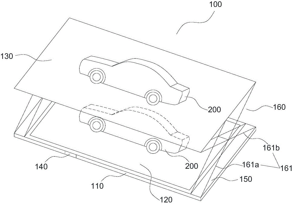
[0049] figure 1 A schematic structural diagram of the parking device 100 provided in this embodiment.

[0050] A parking device 100, comprising a base 110 and a parking platform, the parking platform is a foldable structure, including a bottom parking platform 120 mounted on the base 110, and an upper part above the bottom parking platform 120 mounted on the base 110 Parking platform 130 ; the upper parking platform 130 can move laterally relative to the base 110 to move away from or approach the base 110 , and the upper parking platform 130 can vertically lift relative to the base 110 to fold or unfold. The bottom parking platform 120 is laterally slidable relative to the base 110 to move away from or approach the base 110 .

[0051] Taking typical working steps as an example, the parking method using the parking device 100 is as follows.

[0052] The first stage: install the parking device 100 in the parking area, the entrance of the parking device 100 is parallel or perpe...

Embodiment 2

[0065] see further Figure 4-6 .

[0066] Figure 4-5 Two structural schematic diagrams of the preferred vertical lifting mechanism 150, Figure 6 It is a structural schematic diagram of the first lateral sliding mechanism 150 connected with the base 110 and the vertical lifting mechanism 160 .

[0067] Such as figure 1 , the parking device 100 further includes a circuit control device 140 , and a first lateral sliding mechanism 150 and a vertical lifting mechanism 160 disposed between the upper parking platform 130 and the base 110 . Wherein, the base 110 is set on a support surface, which can be the ground, floor slab or other column and plate structures, for supporting the parking device 100 ; the bottom parking platform 120 is installed on the base 110 . The base 110 is symmetrically provided with two first chutes, each of which is provided with a lateral sliding mechanism and a vertical lifting mechanism, and the upper parking platform 130 passes through the first lat...

Embodiment 3

[0079] Figure 7 It is a schematic structural diagram of the parking device 100 of the three-dimensional compound parking space provided in this embodiment. This embodiment is similar to the second embodiment, except that the bottom parking platform 120 is arranged on the base 110 through the second lateral sliding mechanism 121 . The structure of the second lateral sliding mechanism 121 is similar to that of the first lateral sliding mechanism 150 .

[0080] The working mode of the second lateral sliding mechanism 121 is as follows: the second lateral sliding mechanism 121 drives the bottom parking platform 120 to move out laterally, the car 200 directly drives on the bottom parking platform 120, and then the second lateral sliding mechanism 121 drives the bottom parking platform. The platform 120 is moved in laterally. Compared with the second embodiment, the advantage is: by setting the second lateral sliding mechanism 121, the bottom parking platform 120 can be moved out...


PUM


Abstract

The invention provides a parking device, system and method. The parking device comprises a base and a parking platform. The parking platform is of a detachable structure and comprises a bottom parking platform body installed on the base, at least one layer of upper parking platform body, a transverse sliding mechanism and a vertical lifting mechanism, wherein the transverse sliding mechanism and the vertical lifting mechanism are arranged on the base; the transverse sliding mechanism is used for control the parking platform to be away from or close to the base; and the vertical lifting mechanism is used for supporting the upper parking platform body and controlling the upper parking platform body to go up and down in the perpendicular direction. The vertical lifting mechanism comprises lifting rods and a power transmission mechanism motor; the upper parking platform body can go up and down by adjusting the relative displacement of the ends of the lifting rods; and the transverse displacement of the upper parking platform body is controlled through the first transverse sliding mechanism. The scheme provided by the invention has the advantages that the structure is simple, operation is convenient, and the bearing capacity is high, and parking places on the upper layer and the lower layer are not mutually influenced. The invention further provides the parking system and method utilizing the parking device.

Description

technical field [0001] The invention relates to the technical field of three-dimensional parking equipment, in particular to a foldable parking device, a parking system and a parking method using the parking device. Background technique [0002] With the continuous and rapid development of my country's social economy, the rigid demand for car purchases is strong, and the number of cars continues to grow rapidly. According to statistics from the Traffic Management Bureau of the Ministry of Public Security, as of the end of 2015, there were 40 cities across the country with more than one million cars. 11 The number of cars in each city exceeds 2 million, and the total number of private cars exceeds 124 million, with 31 cars per 100 households, while Beijing, Chengdu, Shenzhen and other big cities have more than 60 private cars per 100 households. [0003] The rapid increase in the number of cars has made the land use in the city more and more tense, especially in many built res...

Claims


Application Information

Patent Timeline
Patent Type & Authority Applications(China)
IPC IPC(8): E04H6/06E04H6/04
CPCE04H6/04E04H6/06
Inventor 廖泽邦马宇尘
Owner NINGBO TOOLSIR ELECTROMECHANICAL CO LTD
Why Eureka
Try Eureka