Harmonic reducer and mechanical arm

A technology of harmonic reducer and manipulator, applied in mechanical equipment, transmission parts, belt/chain/gear, etc., can solve problems such as heat generation, unstable operation, and increased energy consumption

Pending Publication Date: 2017-08-18
杨庆华
View PDF5 Cites 3 Cited by
  • Summary
  • Abstract
  • Description
  • Claims
  • Application Information

AI Technical Summary

Problems solved by technology

There are oil seals in this kind of harmonic reducer, which adopts the method of interference fit with the inner shaft, which will increase the starting torque of the reducer device, and will generate gre...

Method used


Image

  • Harmonic reducer and mechanical arm
  • Harmonic reducer and mechanical arm
  • Harmonic reducer and mechanical arm

Examples


Embodiment 1

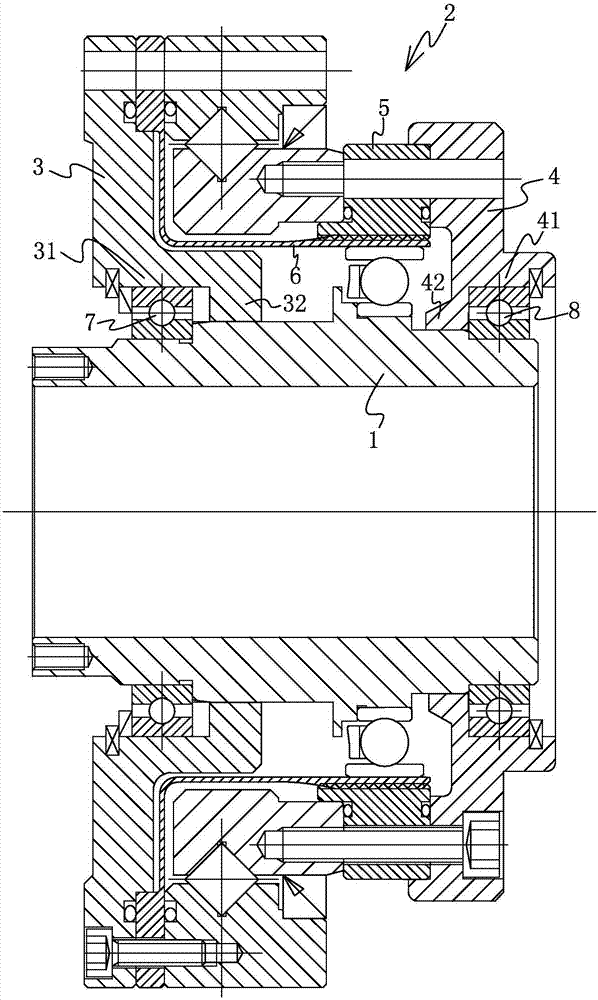
[0027] Such as figure 1 As shown, the harmonic reducer includes a hollow inner shaft 1 and a casing 2 located outside the inner shaft 1 . Among them, the inner shaft 1 is used as the input end of the wave generator in the reducer. When the harmonic reducer is in operation, the inner shaft 1 rotates relative to the outer shell 2 inside the outer shell 2 .

[0028] The casing 2 includes end caps one 3 and two end caps 4 , both of which are ring-shaped and sleeved on the inner shaft 1 . There is a cavity between the end cover one 3 and the end cover two 4 for setting the steel wheel 5 and the flexible wheel 6, that is to say, the steel wheel 5 and the flexible wheel 6 are located inside the end cover one 3 and the end cover two 4 . Lubricating grease is filled between the end cap one 3 and the end cap two 4 .

[0029] Wherein, the end cover one 3 has a part one 31 and a part two 32, a bearing one 7 is arranged between the part one 31 and the inner shaft 1, and a gap seal is f...

Embodiment 2

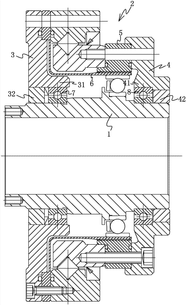
[0035] This embodiment is substantially the same as Embodiment 1, the difference is that in this embodiment, if figure 2 As shown, on the end cover 3, the part 2 32 is located inside the part 1 31; on the end cover 2 4, the part 4 42 is located inside the part 3 41. Such a structure, on the one hand, makes the cavity between the first end cover 3 and the second end cover 4 smaller, reducing the use of lubricating substances, and on the other hand, makes the structure of the harmonic reducer more compact.

[0036] According to the purpose of the present invention, the present invention also proposes a kind of manipulator that runs smoothly, and its technical scheme is as follows:

[0037] Manipulator, including the above-mentioned harmonic reducer.


PUM


Abstract

The invention discloses a harmonic reducer and a mechanical arm, belongs to the technical field of harmonic reducers. The harmonic reducer and the mechanical arm solve the problems that the starting torque of an existing harmonic device is large, the starting current of a motor is large, the carrying capacity of a mechanical arm is not large, and the operation is not stable. The harmonic reducer is characterized by comprising an inner shaft and an outer shell positioned on the outer side of the inner shaft, the outer shell comprises a first end cover which is annular and is arranged on the inner shaft in a sleeving mode, a rigid gear and a flexible gear are arranged on the inner side of the first end cover, a first part and a second part are arranged on the first end cover, a first bearing is arranged between the first part and the inner shaft, and the second part and the inner shaft are in clearance gap seal. According to the harmonic reducer and the mechanical arm, the second part on the first end cover and the inner shaft are of a clearance gap seal structure, and a fourth part on a second end cover and the inner shaft are of a clearance gap seal structure so that the starting torque of the harmonic device can be small, the starting current of the motor can be small, and meanwhile, the carrying capacity and the stable operation of the mechanical arm can be improved.

Description

technical field [0001] The invention belongs to the technical field of harmonic reducers. Background technique [0002] Chinese utility model patent (publication number: CN204961720U, public date: 2016.01.13) discloses a hollow reducer, including a wave generator, a first bearing, a first oil seal, a top end cover, a flexible wheel, a steel wheel, a second Oil seal, crossed roller outer ring, crossed roller inner ring, bottom end cover, third oil seal, second bearing and third bearing, etc. It is characterized in that the wave generator has a third bearing, and the third bearing has a Soft spline, the soft spline coat has steel wheel. Among them, the first oil seal is placed outside the wave generator and above the first bearing, and the outer ring is pressed and fixed by the top end cover; the cross roller inner ring is embedded between the steel wheel and the bottom end cover, and the upper outer ring The second oil seal is tightly connected; the cross roller outer ring ...

Claims


Application Information

Patent Timeline
IPC IPC(8): F16H49/00F16H57/031F16H57/023F16H57/029
CPCF16H49/00F16H57/023F16H57/029F16H57/031
Inventor 杨庆华
Owner 杨庆华
Why Eureka
Try Eureka