Method and system for measuring AC resistance of conductor

A technology of AC resistance and measuring system, which is applied in measuring devices, measuring electrical variables, measuring resistance/reactance/impedance, etc., can solve the problems of unknown accuracy, difficult to guarantee accuracy, operability and low accuracy, and achieve The effect of high accuracy and convenient operation

Active Publication Date: 2017-08-18
ELECTRIC POWER RESEARCH INSTITUTE, CHINA SOUTHERN POWER GRID CO LTD +1
View PDF6 Cites 7 Cited by
  • Summary
  • Abstract
  • Description
  • Claims
  • Application Information

AI Technical Summary

Problems solved by technology

[0003] The test techniques used in traditional AC resistance measurement can be divided into two categories: thermal measurement and electrical measurement. Thermal measurement can make absolute and relative measurements and each measurement can be used for steady state and transient conditions, but thermal measurement requires Put the wire to be tested in a constant temperature environment, otherwise the accuracy is still unknown, and there will be difficulties in heat insulation and measurement; the electrical measurement method requires many instruments, such as power meters and potentiometers, etc. The principle is to measure the wire at power frequency and The voltage and current at the maximum design temperature, using the four-point measurement method, requires skilled operators and a long time to ensure both measurement and accuracy
The traditional AC resistance measurement process is complex and difficult to guarantee accuracy, and the operability and accuracy are low

Method used


Image

  • Method and system for measuring AC resistance of conductor
  • Method and system for measuring AC resistance of conductor
  • Method and system for measuring AC resistance of conductor

Examples


Embodiment Construction

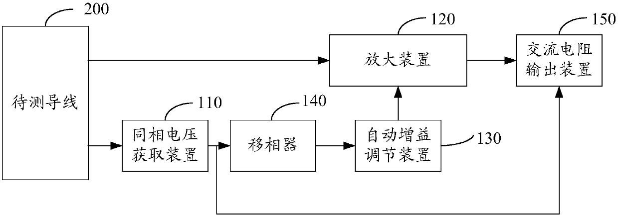
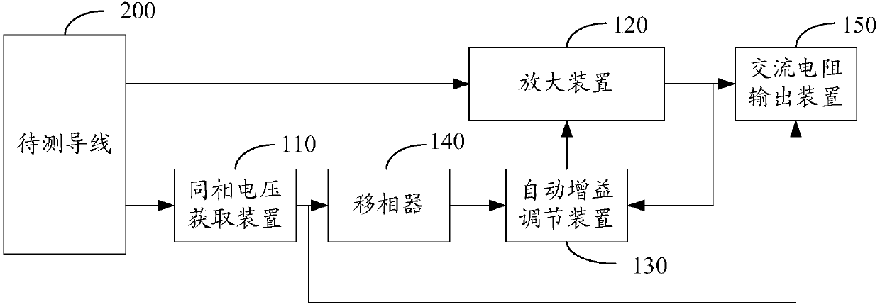
[0024] In one embodiment, such as figure 1 As shown, a conductor AC resistance measurement system includes an in-phase voltage acquisition device 110, an amplification device 120, an automatic gain adjustment device 130, a phase shifter 140 and an AC resistance output device 150, and the in-phase voltage acquisition device 110 is connected to the phase shifter 140, It is also used to connect the wire 200 to be tested, the amplifier 120 is connected to the AC resistance output device 150, and is also used to connect the wire 200 to be tested, the phase shifter 140 is connected to the automatic gain adjustment device 130, and the automatic gain adjustment device 130 is connected to the amplifier 120. The resistance output device 150 is connected to the common terminal of the in-phase voltage acquisition device 110 and the phase shifter 140. The in-phase voltage acquisition device 110 is used to convert the measured current flowing through the wire 200 to be tested into a first in...


PUM


Abstract

The invention relates to a method and system for measuring the AC resistance of a conductor. The system comprises an in-phase voltage acquisition device, an amplification device, an automatic gain adjustment device, a phase shifter and an AC resistance output device. The in-phase voltage acquisition device is connected with a wire to be measured and the phase shifter. The amplification device is connected with the wire to be measured and the AC resistance output device. The phase shifter is connected with the automatic gain adjustment device. The automatic gain adjustment device is connected with the amplification device. The AC resistance output device is connected with the common end of the in-phase voltage acquisition device and the phase shifter, measures the current flowing through the wire to be measured and the voltage drop of the wire to be measured simultaneously, and converts the current flowing through the wire to be measured into first in-phase voltage. The phase shifter, the amplification device, and the automatic gain adjustment device process the voltage drop and the first in-phase voltage to obtain a voltage component. The AC resistance of the wire to be measured is calculated according to the voltage component in the voltage drop of the wire to be measured and the first in-phase voltage. The method and system have no requirement for test environment, and are convenient in operation and high in accuracy.

Description

technical field [0001] The invention relates to the technical field of high-voltage equipment and testing, in particular to a method and system for measuring the AC resistance of a conductor. Background technique [0002] With the development of the national economy, the demand for electricity is increasing. In order to improve the current-carrying capacity, the conductor cross-sectional area of ​​the overhead lines and high-voltage cables produced is getting larger and larger to meet the demand of power growth. For AC systems, the essence of improving current carrying capacity is to reduce the AC resistance of overhead lines and cables. In addition to DC resistance, it also includes resistance increments caused by alternating electromagnetic fields. The sum of them is AC resistance. As conductors become larger in size, the non-uniform distribution of current along the cross-section of conductors due to skin effect and proximity effect significantly increases their AC resis...

Claims


Application Information

Patent Timeline
Patent Type & Authority Applications(China)
IPC IPC(8): G01R27/08
CPCG01R27/08
Inventor 罗勇芬刘良帅王国利李斌刘磊厉天威
Owner ELECTRIC POWER RESEARCH INSTITUTE, CHINA SOUTHERN POWER GRID CO LTD
Why Eureka
Try Eureka