
Display panel and display device

A display panel and display area technology, applied in the field of microelectronics, can solve the problems of affecting the curing of the sealant and the decrease of the transmittance of the sealant.

Active Publication Date: 2017-08-18
SHANGHAI AVIC OPTOELECTRONICS
View PDF9 Cites 8 Cited by
  • Summary
  • Abstract
  • Description
  • Claims
  • Application Information

AI Technical Summary

Problems solved by technology

[0005] However, in the actual process, it is also necessary to use a sealant to be coated in the fan-out area to bond the array substrate and the color filter substrate in the display panel. The coverage of the wiring gap between the touch signal line and the data line makes the sealing The transmittance of the frame sealant decreases between the wiring gaps, which affects the curing of the sealant

Method used


Image

  • Display panel and display device
  • Display panel and display device
  • Display panel and display device

Examples


Embodiment Construction

[0025] In order to better understand the technical solutions of the present invention, the embodiments of the present invention will be described in detail below in conjunction with the accompanying drawings.

[0026] It should be clear that the described embodiments are only some of the embodiments of the present invention, not all of them. Based on the embodiments of the present invention, all other embodiments obtained by persons of ordinary skill in the art without creative efforts fall within the protection scope of the present invention.

[0027] Terms used in the embodiments of the present invention are only for the purpose of describing specific embodiments, and are not intended to limit the present invention. As used in the embodiments of the present invention and the appended claims, the singular forms "a", "said" and "the" are also intended to include the plural forms unless the context clearly indicates otherwise.

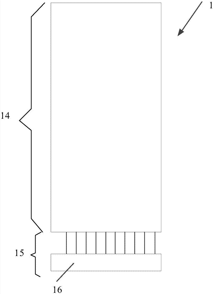
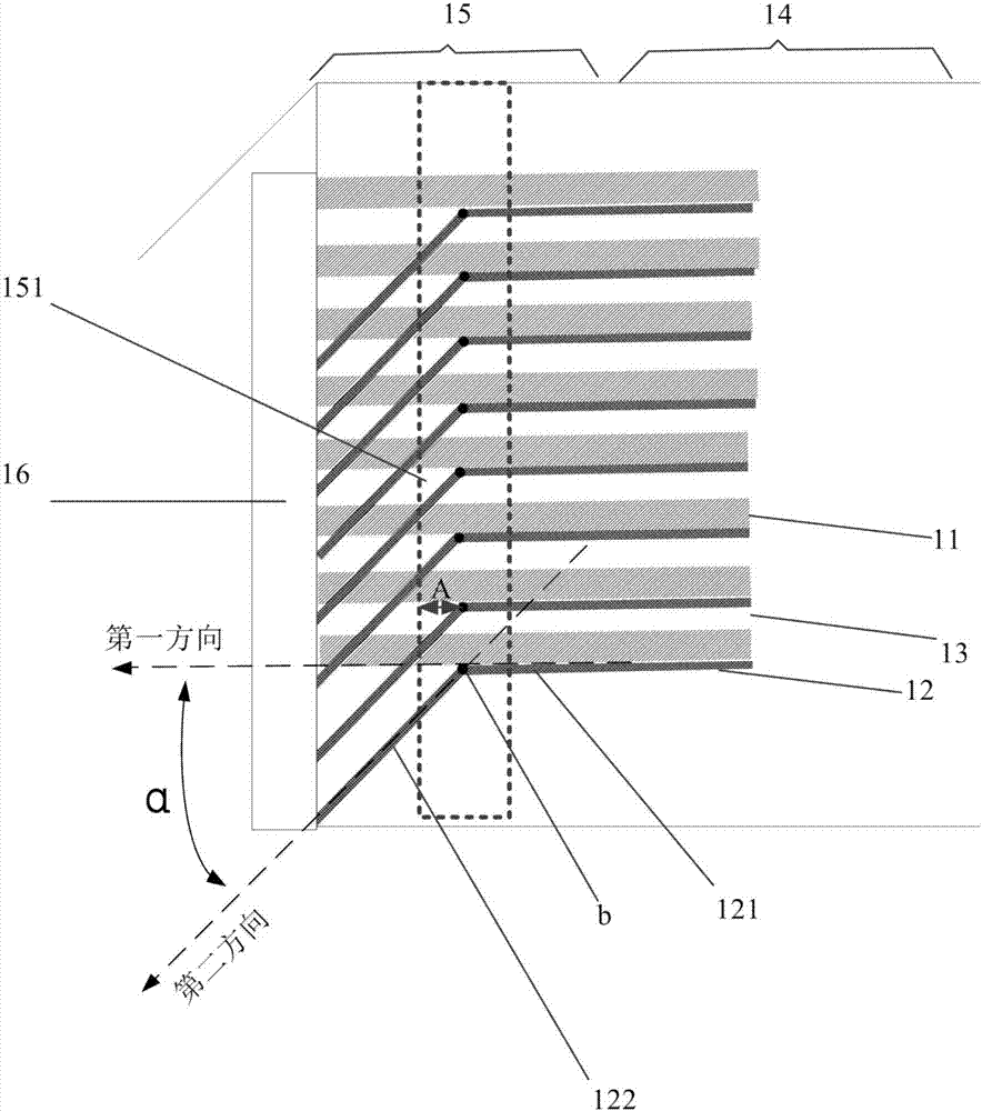
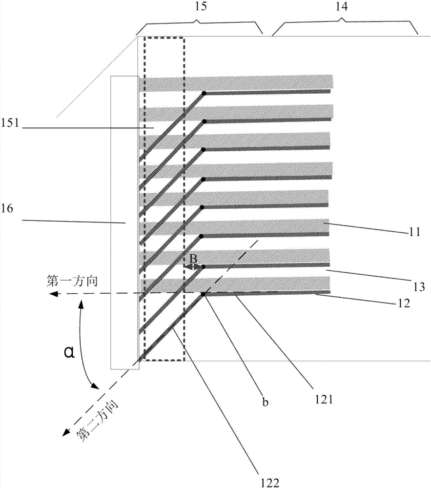
[0028] figure 1 An overall schematic diagram of...


PUM


Abstract

The invention provides a display panel and a display device. The display panel includes a display region and a fan-out region. The fan-out region includes a frame sealing glue coating region. The display panel also includes a plurality of first signal lines, a plurality of second signal lines and a driving circuit; the first signal lines and the second signal lines extend from the display region to the fan-out region and are electrically connected to the driving circuit; the first signal lines extend in the first direction and pass through the frame sealing glue coating region; at least one second signal line includes a first section and a second section which are positioned in the fan-out region, the first section and the second section are connected through a first node, the first section extends in the first direction, a projection of the first section and wiring clearance projections of the first signal lines have overlapped portions, the second section extends in the second direction, and a first included angle is formed between the first direction and the second direction. The technical scheme can increase the transmittance of the frame sealing glue, can improve the frame sealing effect, and can reinforce the display panel.

Description

[0001] 【Technical field】 [0002] The present invention relates to the technical field of microelectronics, in particular to a display panel and a display device. [0003] 【Background technique】 [0004] The display panels of electronic devices such as mobile phones realize the touch function by multiplexing the common electrodes as touch electrodes. For example, a self-capacitive capacitive touch screen adds a layer of touch signal lines, which are connected to the common electrodes arranged in a matrix through via holes. , for touch functionality. At the same time, the data lines of the display area are connected to the driving circuit through the connection lines of the fanout area, so as to realize the display function. In order to facilitate wiring, the touch signal lines generally pass through the fan-out area in parallel with the data lines. Wherein, since the widths of the touch signal lines and the data lines are inconsistent, the touch signal lines will cover the wi...

Claims


Application Information

Patent Timeline
Patent Type & Authority Applications(China)
IPC IPC(8): G02F1/1345G09F9/00G06F3/041G06F3/044
CPCG02F1/1345G06F3/0412G06F3/044G09F9/00
Inventor 朱雪婧金慧俊
Owner SHANGHAI AVIC OPTOELECTRONICS
Learn More