Preparation method of crystalline silicon SE solar cell and crystalline silicon SE solar cell

A technology of solar cells and crystalline silicon, which is applied in the field of solar cells, can solve the problems of uniform diffusion of crystalline silicon SE solar cells and difficulties in printing alignment, and achieve high photoelectric conversion efficiency, fine grid lines, and small series resistance.

Active Publication Date: 2014-03-26
SHANGHAI BYD
View PDF5 Cites 9 Cited by
  • Summary
  • Abstract
  • Description
  • Claims
  • Application Information

AI Technical Summary

Problems solved by technology

[0005] The invention solves the technical problems of uniform diffusion and difficult printing alignment in the preparation of crystalline silicon SE solar cells in the prior art, and provides a simple process, low cost, large-scale production, and improved photoelectric conversion efficiency. Crystalline silicon SE solar battery sheet and preparation method thereof

Method used


Image

  • Preparation method of crystalline silicon SE solar cell and crystalline silicon SE solar cell

Examples


preparation example Construction

[0015] The invention provides a method for preparing a crystalline silicon SE solar cell, comprising the following steps:

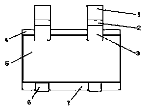
[0016] S1. Carry out texturing, diffusion, and dephosphorous silicon glass treatment on the surface of the silicon wafer 5, and then coat the silicon nitride anti-reflection film 4 on the front surface of the silicon wafer 5;

[0017] S2, covering one layer of metal mask on the surface of anti-reflection film 4, the shape of the hollow part of the metal mask is the same as the shape of the electrode grid line on the light-facing surface; then adopt magnetron sputtering to deposit oxidation on the anti-reflection film 4 Bismuth, the metal mask is removed after sputtering to obtain a bismuth oxide gate line layer;

[0018] S3. Print the back silver conductive paste on the back of the silicon wafer 5, print the back field aluminum paste after drying, sinter the silicon wafer as a whole in a tunnel furnace after drying, and perform annealing treatment after s...

Embodiment 1

[0043] (1) Texture-making, cleaning and drying, organophosphorus diffusion, etching, and phosphorus-silicon glass removal are carried out on the P-type polysilicon of 156×156mm, and then silicon nitride anti-reflection coating is coated on the front of the silicon wafer to obtain a P-type polysilicon wafer .

[0044] (2) Put the P-type polysilicon wafer on the loading table of the linear magnetron sputtering machine, cover the front with a metal molybdenum mask, fix the P-type polysilicon wafer and the metal molybdenum mask, and then place it as a whole. into the sputtering chamber, sputtering with bismuth oxide (purity > 99.9wt%) pre-fixed in the chamber as the target, close the door of the sputtering chamber, and vacuum the chamber such as argon, the sputtering pressure The temperature is 0.7Pa, the argon flow rate is 15sccm, the silicon wafer temperature is 240°C, and the sputtering time is 20s. After the sputtering is completed, remove the metal molybdenum mask plate to re...

Embodiment 2

[0049] The same steps as in Example 1 were used to prepare the crystalline silicon SE solar cell of this example, the difference being that:

[0050] In step (2), the P-type polysilicon wafer is placed on the loading table of the linear magnetron sputtering machine, and its front is covered with a metal molybdenum mask plate, and the P-type polysilicon wafer and the metal molybdenum mask plate are fixed, and then Put it into the sputtering chamber as a whole, use bismuth oxide (purity>99.9wt%) pre-fixed in the chamber as the target for sputtering, close the door of the sputtering chamber, vacuum the chamber and introduce argon gas , the sputtering pressure is 0.6Pa, the argon flow rate is 18sccm, the silicon wafer temperature is 240°C, and the sputtering time is 30s. After the sputtering is completed, remove the metal molybdenum mask to realize the oxidation of the gate line area of ​​the P-type polysilicon wafer. Deposition of bismuth film, the thickness of the deposited bism...


PUM

PropertyMeasurementUnit
thicknessaaaaaaaaaa
thicknessaaaaaaaaaa
widthaaaaaaaaaa

Abstract

The invention provides a preparation method of a crystalline silicon SE solar cell. The preparation method comprises the following steps: (S1) the wool making, the dispersion and the phosphorosilicate glass removal treatments are implemented for the surface of a silicon slice; then a silicon nitride antireflection film is plated on the frontal surface of the silicon slice; (S2) one layer of metal mask is covered on the surface of the antireflection film; then bismuth oxide is deposited on the antireflection film by adopting the magnetron sputtering method; (S3) back surface silver conductive paste and back field aluminum paste are printed on the back surface of the silicon slice; the whole body is introduced in a tunnel kiln for sintering; the annealing is implemented after finishing the sintering; (S4) the photoinduction electroplating is implemented on the frontal surface of the silicon slice to obtain the crystalline silicon SE solar cell. The preparation method, provided by the invention, has the advantage of simple process, low cost and capability of realizing large-scale production; the prepared crystalline silicon SE solar cell has the benefits of fine surface electrode grid lines, small covering area, low cell serial connection resistance, increased fill factor, high photoelectric converting efficiency and low cost.

Description

technical field [0001] The invention belongs to the technical field of solar cells, and in particular relates to a method for preparing a crystalline silicon SE solar cell and a crystalline silicon SE solar cell prepared by the preparation method. Background technique [0002] As a kind of green energy, solar energy has attracted more and more attention due to its advantages of inexhaustibility, no pollution, and no limitation of geographical resources. Existing crystalline silicon solar cells generally use screen printing conductive paste on the silicon substrate, drying and firing to prepare electrodes and back field. The light-facing surface of crystalline silicon solar cells is screen-printed with front silver paste after anti-reflection coating, and then sintered in a tunnel furnace to directly obtain front silver electrodes. The production of front electrodes can significantly affect the light acceptance rate, thereby affecting the battery performance. Short-circuit c...

Claims


Application Information

Patent Timeline
Patent Type & Authority Applications(China)
IPC IPC(8): H01L31/18H01L31/0224
CPCH01L21/225H01L31/022433H01L31/1804Y02E10/547Y02P70/50
Inventor 谭伟华
Owner SHANGHAI BYD
Why Eureka
Try Eureka