Light source device and projector

一种光源装置、固体光源的技术,应用在光源、放映装置、点状光源等方向,能够解决半导体激光器冷却效率下降、难以半导体激光器组装在印刷电路板上等问题,达到稳定配置、高效冷却、提高位置精度的效果

Active Publication Date: 2013-02-13
SEIKO EPSON CORP
View PDF7 Cites 8 Cited by
  • Summary
  • Abstract
  • Description
  • Claims
  • Application Information

AI Technical Summary

Problems solved by technology

In such a configuration, since it is necessary to provide a base corresponding to the semiconductor laser, there is a problem that it is difficult to tightly assemble the semiconductor laser on the printed circuit board.
Also, when the semiconductor laser is assembled on a printed circuit board without a base, since the semiconductor laser is separated from the printed circuit board, it becomes impossible to properly release the heat generated in the semiconductor laser. The cooling efficiency drops such a problem

Method used


Image

  • Light source device and projector
  • Light source device and projector
  • Light source device and projector

Examples


no. 1 Embodiment approach

[0051] Hereinafter, a first embodiment of the present invention will be described based on the drawings.

[0052] The overall composition of the projector

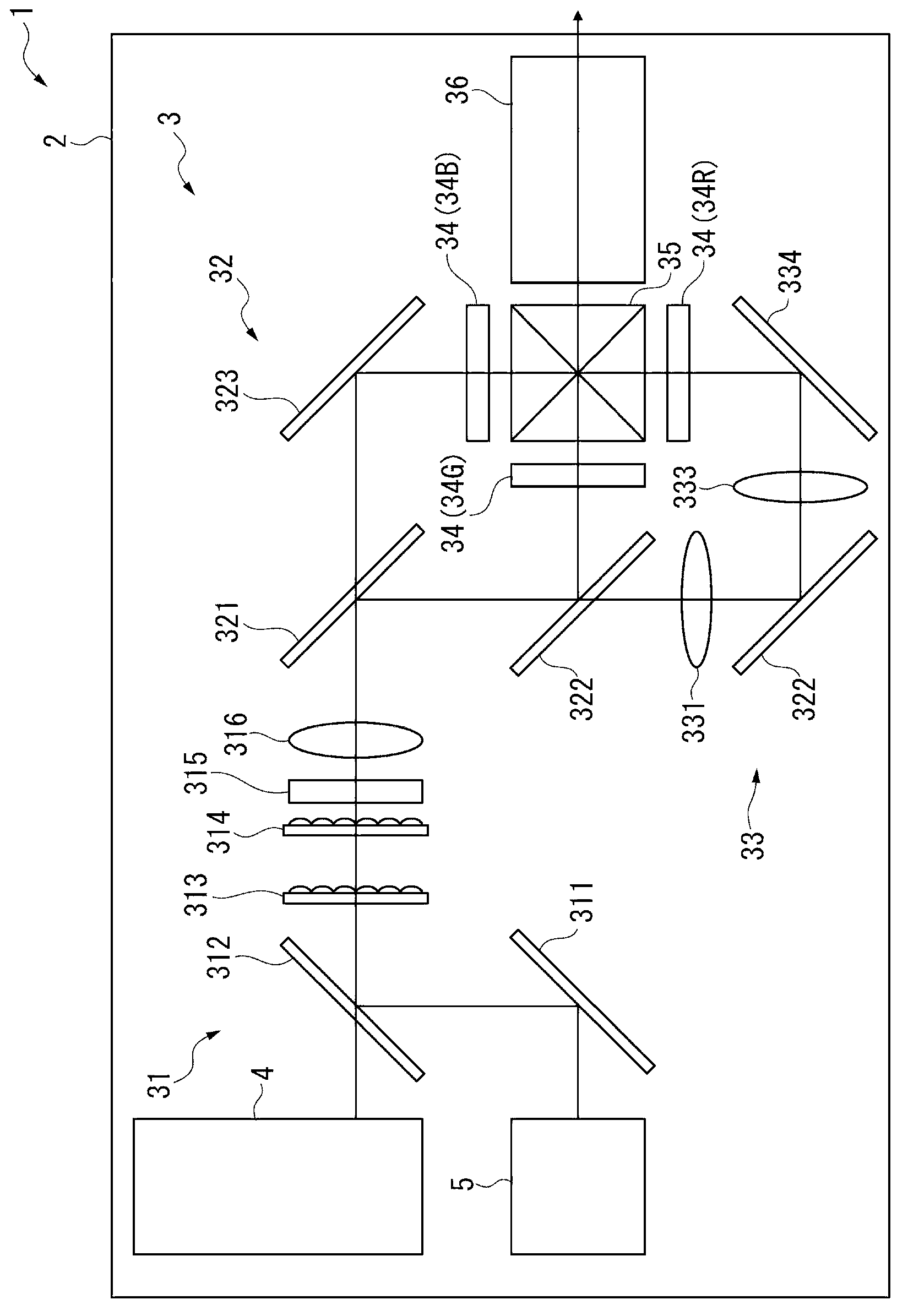
[0053] The projector 1 according to this embodiment is a projector that modulates a light beam emitted from a light source device installed inside to form an image corresponding to image information, and enlarges and projects the image on a projection surface such as a screen. Such a projector 1, such as figure 1 As shown, there are a metal or synthetic resin housing 2 and an optical device 3 accommodated in the housing 2 . In addition, the illustration is omitted, but the projector 1 also includes: a control device for controlling the operation of the projector 1; a power supply device for supplying electric power to the electronic components constituting the projector 1; and cooling devices such as a cooling light source device. Object cooling device, etc.

[0054] The composition of the optical device

[0055] The o...

no. 2 Embodiment approach

[0145] Hereinafter, a second embodiment of the present invention will be described.

[0146] The projector of this embodiment has the same configuration and functions as the projector 1 described above, but differs from the projector 1 in that each solid light source 411 is pressed and fixed to the base member 412 by a single pressing member.

[0147] In addition, in the following description, the same code|symbol is attached|subjected to the part which is the same or substantially the same as what was already demonstrated, and description is abbreviate|omitted.

[0148] Figure 8 It is a plan view showing the pressing member 612 of the projector according to this embodiment.

[0149] The projector according to this embodiment has the same configuration and function as the projector 1 except that a plurality of pressing members 612 are provided instead of the pressing member 414 and the fixing member 415 .

[0150] These pressing parts 612, such as Figure 8 As shown, it ha...

no. 3 Embodiment approach

[0157] Next, a third embodiment of the present invention will be described.

[0158] The projector according to this embodiment has the same configuration and functions as the above-mentioned projector 1 . Here, in this projector 1, the extension direction of the protrusion 4142 protruding from the edge of the opening 4141 in the pressing member 414 is set to intersect the X direction and the Y direction, that is, the row direction and the column direction. However, the projector according to this embodiment , the extension direction is parallel to the row direction. In this point, the projector according to this embodiment is different from the projector 1 . In addition, in the following description, the same code|symbol is attached|subjected to the part which is the same or substantially the same as what was already demonstrated, and description is abbreviate|omitted.

[0159] Figure 9 It is a plan view showing the pressing member 613 of the projector according to this e...


PUM


Abstract

A light source device includes a plurality of solid-state light sources, and a base member on which the plurality of solid-state light sources are provided, wherein each of the solid-state light sources includes a stem on which a light-emitting element is provided and terminals connected to the light-emitting element, and the base member includes a hole portion into which one of the terminals is inserted and a planar portion that is in contact with the stem.

Description

technical field [0001] The present invention relates to a light source device and a projector, in particular, to a light source device and a projector having a solid light source. Background technique [0002] Conventionally, there is known a projector comprising: a light source device; a light modulation device for modulating light emitted from the light source device to form an image corresponding to image information; and a projection optical device for enlarging and projecting the light on a projected surface such as a screen. image. [0003] As such a light source device, a light source device having a discharge light source lamp such as an ultra-high pressure mercury lamp is used. However, in recent years, light source devices having a solid-state light source have begun to be used due to demands for power saving. As such a light source device, a light source device having a solid-state light source such as an LED (Light Emitting Diode) and an LD (Laser Diode: Laser D...

Claims


Application Information

Patent Timeline
Patent Type & Authority Applications(China)
IPC IPC(8): G03B21/20G03B21/00F21V19/00F21V29/00F21Y101/02
CPCG03B21/00G03B21/204G03B33/12G03B21/16G03B21/2013
Inventor 座光寺诚长谷要和田将
Owner SEIKO EPSON CORP
Why Eureka
Try Eureka